
Wrench-type clip for folder

A technology of folders and clips, which is applied to folders, applications, household stoves, etc., can solve the problems of operating folder damage and damage, and achieve the effect of preventing accidental damage

Inactive Publication Date: 2007-11-21
WORLD WIDE STATIONARY MFG CO LTD
View PDF3 Cites 0 Cited by
  • Summary
  • Abstract
  • Description
  • Claims
  • Application Information

AI Technical Summary

Problems solved by technology

[0004] A disadvantage of the existing wrench type clamp is that the other end arm of the rotating arm passes through the hole in the side wall of the bead, and the end of the end arm protrudes outside the side wall of the bead, as shown in Figure 1A
In this way, when the document page is rolled and pressed, the end of the arm protruding outside the side wall of the bead can easily damage the rolled document page, as shown in Figure 2 and Figure 2A
[0005] A disadvantage of existing wrench-type clips is that at

Method used


Image

  • Wrench-type clip for folder
  • Wrench-type clip for folder
  • Wrench-type clip for folder

Examples


Example Embodiment

[0040] Figures 4-9 describe the first embodiment of the invention. The structure and working principle of the first embodiment of the present invention are basically the same as those of the existing wrench-type clamp, and will not be described in detail here, but only the improvements of the present invention will be described in detail.

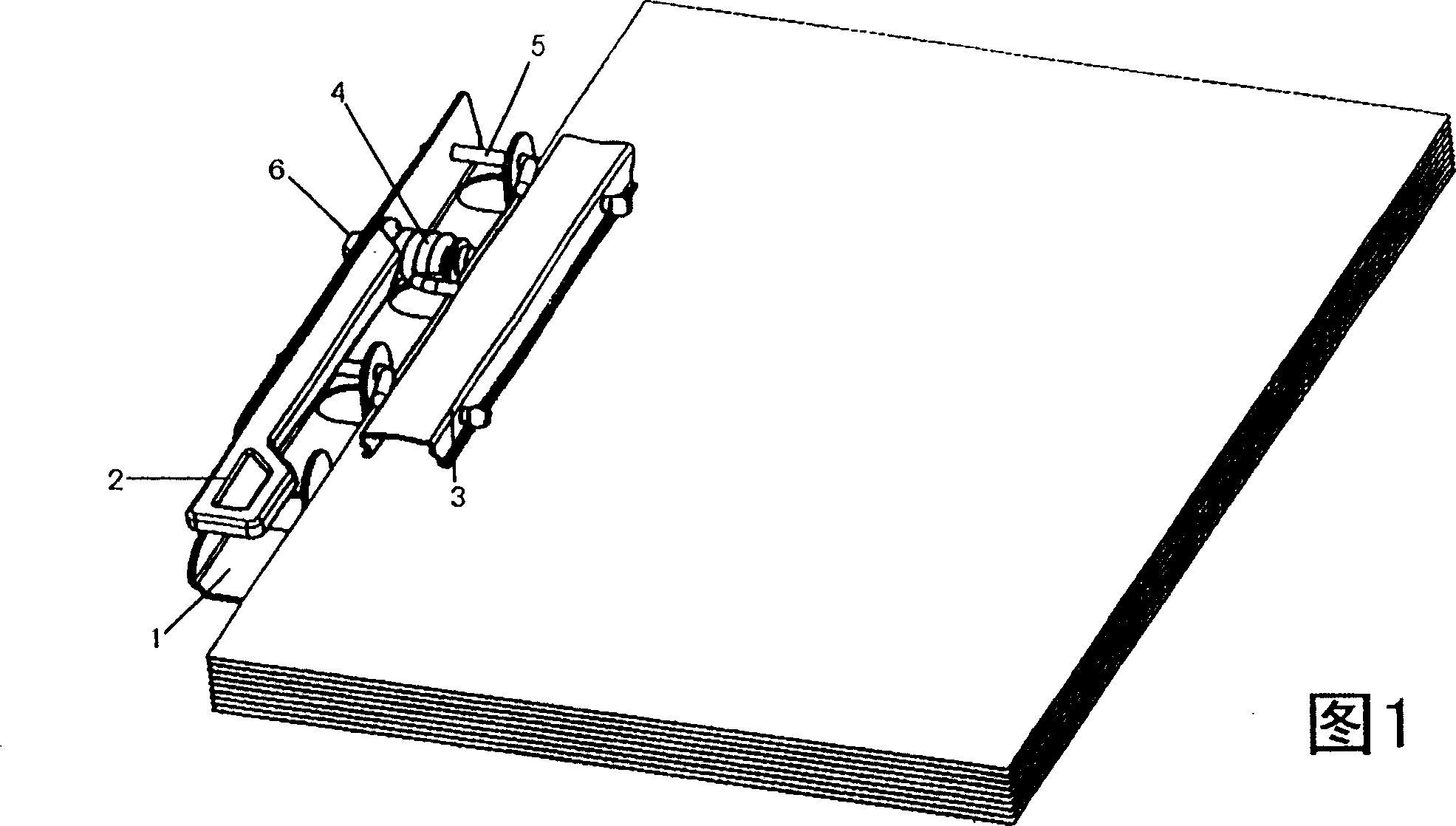
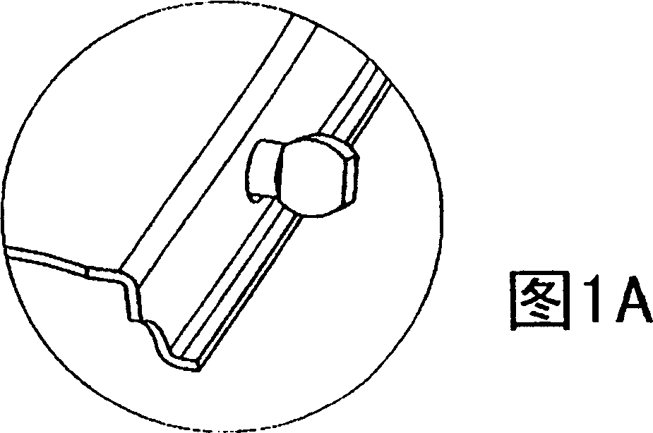
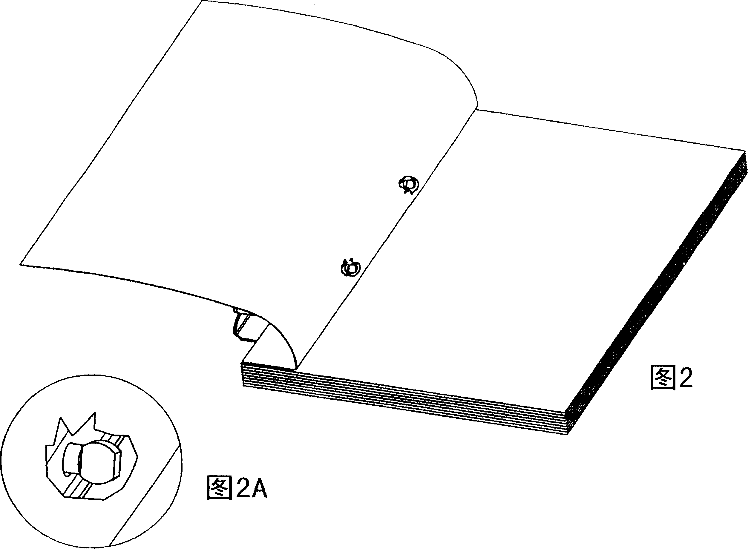
[0041]As shown in FIG. 7, the wrench type clip of the first embodiment of the present invention includes a bottom plate 1, a handle 2, a pressure bar 3, a torsion spring 4, a rotating arm 5 and a pin 6. The bottom plate 1 has a flat L-shaped cross-sectional structure formed by a vertical side wall part and a bottom wall part, and a plurality of cuts from the bottom wall are formed on the substantially middle position of the bottom wall of the bottom wall and facing each other. The tab 7 bent to the vertical position on the bottom wall. The part on the side wall corresponding to the convex piece 7 is concavely curved inward to form a cut concave...


PUM


Abstract

The present invention provides a wrench-type clip for folder. By means of the support part on the side wall of chip base board and the corresponding structure set on the hold down strip, the ends of the rotary arms will not extend beyong the side wall or the base board or the outer side wall of the hold down strip, and this can avoid effectively the damage to extending ends of turned file and theinjury to hand.

Description

technical field [0001] The present invention relates to a wrench type clip for folders. Background technique [0002] Referring now to FIG. 1, a prior art wrench grip for folders is illustrated. The wrench type clip includes a metal bottom plate 1, a handle 2, a metal bead 3, a torsion spring 4, a rotating arm 5 and a pin 6. The bottom plate 1 has a flat L-shaped cross-sectional structure formed by a vertical side wall portion and a bottom wall portion, on which a plurality of cutting holes are cut from the bottom wall and bent to be vertical relative to the bottom wall. location tabs. The pin 6 passes through the hole formed on the side wall and the lug corresponding to each other and is fixedly installed on the side wall and the lug. The torsion spring 4 is installed on the pin 6, and one end of the torsion spring 4 leans against the bottom surface of the handle 2. The other end is connected to the pressing bar 3 so as to exert spring biasing force on the pressing bar 3...

Claims


Application Information

Patent Timeline
IPC IPC(8): B42F9/00
CPCF24C3/008F24C15/2021
Inventor 杜振源吴荣耀郑可平
Owner WORLD WIDE STATIONARY MFG CO LTD
Features
  • Generate Ideas
  • Intellectual Property
  • Life Sciences
  • Materials
  • Tech Scout
  • Unparalleled Data Quality
  • Higher Quality Content
  • 60% Fewer Hallucinations
Learn More