Check patentability & draft patents in minutes with Patsnap Eureka AI!

Cuff for blood pressure meter and blood pressure meter with the same

A sphygmomanometer and cuff technology, applied in the direction of catheters, etc., can solve problems such as complicated operation

Inactive Publication Date: 2007-12-12
TERUMO KK
View PDF4 Cites 1 Cited by
  • Summary
  • Abstract
  • Description
  • Claims
  • Application Information

AI Technical Summary

Problems solved by technology

Therefore, when there is a deviation in the overlapping position, the fasteners have to be disassembled again and again, and then they are overlapped again. In this way, the operation of correctly aligning the scale 51 or the index 61 with the reference positions 52, 62 is more complicated.

Method used


Image

  • Cuff for blood pressure meter and blood pressure meter with the same
  • Cuff for blood pressure meter and blood pressure meter with the same
  • Cuff for blood pressure meter and blood pressure meter with the same

Examples


Embodiment Construction

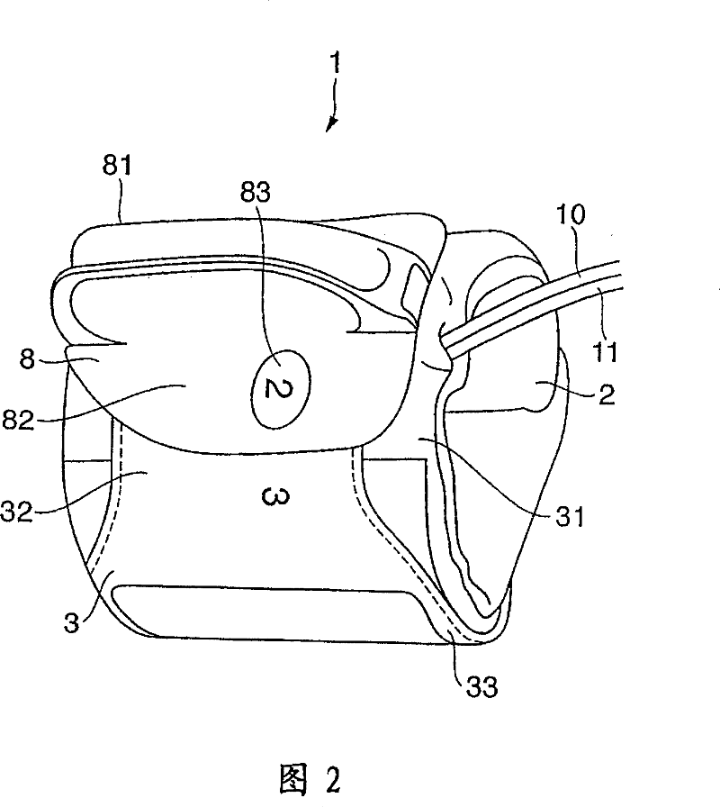
[0047] The cuff for a sphygmomanometer of the present invention will be described in detail below according to the preferred embodiments shown in the accompanying drawings. In addition, in this embodiment, the measurement site is the upper arm.

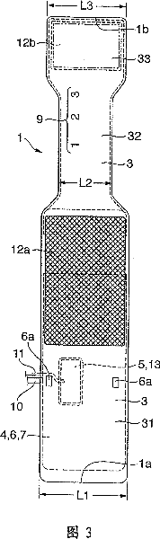
[0048] Fig. 2 is a perspective view of the ferrule of this embodiment. 3 and 4 are views of the ferrule of FIG. 2 removed from the window frame-like part of the ferrule and formed into an expanded shape, viewed from the outer surface and the inner surface, respectively. Figure 5 is a perspective view of a curved plate built into a ferrule. 6A, 6B are a perspective view from above and a perspective view from below, respectively, of the window frame-like member mounted on the ferrule. Fig. 7 is a view for adjusting the coiled state of the ferrule (cylindrical diameter of the ferrule). 8A and 8B are views in which the thickness of the measurement site (upper arm) is adjusted to be thinner and thicker than the standard setting, respect...


PUM


Abstract

A cuff for a blood pressure meter, where, in blood pressure measurement, a winding state of the cuff in accordance with the size of a portion to be measured can be set by simple operation. The cuff for a blood pressure meter has marks indicating a winding state of the cuff in accordance with the circumferential length of a portion to be measured and a window frame member (8) selectively indicating one of the marks. When a cuff portion (32) where the marks are provided slides between the window frame member (8) and an external surface of a cuff portion (31) to which the window frame member (8) is attached, the one of the marks is selectively indicated through a window (83) of the window frame member. This makes it possible that a winding state of the cuff (diameter of the cuff in a tubular shape) in accordance with the circumferential length (size) of a portion to be measured is adjusted and set by simple operation.

Description

technical field [0001] The present invention relates to the technical field of a cuff for a sphygmomanometer installed on a measurement site such as the upper arm of a measurer to measure blood pressure and a sphygmomanometer provided with the cuff. Background technique [0002] Regarding the cuff of the sphygmomanometer, in the past, it was believed that by setting a scale in the length direction of the cuff or setting an index that can slide freely along the length of the cuff or be freely installed at any position, the The length corresponds to the setting of the cuff winding state (cylindrical diameter of the cuff) at the time of blood pressure measurement. [0003] For example, Japanese Patent Laid-Open Publication No. Hei 8-229010 discloses such a cuff for a sphygmomanometer. However, in the sphygmomanometer cuffs 50, 60 (FIGS. 1A and 1B) described in the above publication, when the scale 51 or the index 61 is made to overlap the reference positions 52, 62, at the sam...

Claims


Application Information

Patent Timeline
Patent Type & Authority Patents(China)
IPC IPC(8): A61B5/02
Inventor 宇野拓也小泽仁望月宽
Owner TERUMO KK
Features
  • R&D
  • Intellectual Property
  • Life Sciences
  • Materials
  • Tech Scout
  • Unparalleled Data Quality
  • Higher Quality Content
  • 60% Fewer Hallucinations
Learn More