
Connector

A technology of connectors and substrates, which is applied in the direction of connections, parts of connecting devices, electrical components, etc., can solve problems such as the reduction of the overall strength of the casing

Inactive Publication Date: 2013-10-30
JAPAN AVIATION ELECTRONICS IND LTD +1
View PDF7 Cites 0 Cited by
  • Summary
  • Abstract
  • Description
  • Claims
  • Application Information

AI Technical Summary

Problems solved by technology

Therefore, the overall strength of the housing can be reduced

Method used


Image

  • Connector
  • Connector
  • Connector

Examples


no. 1 example

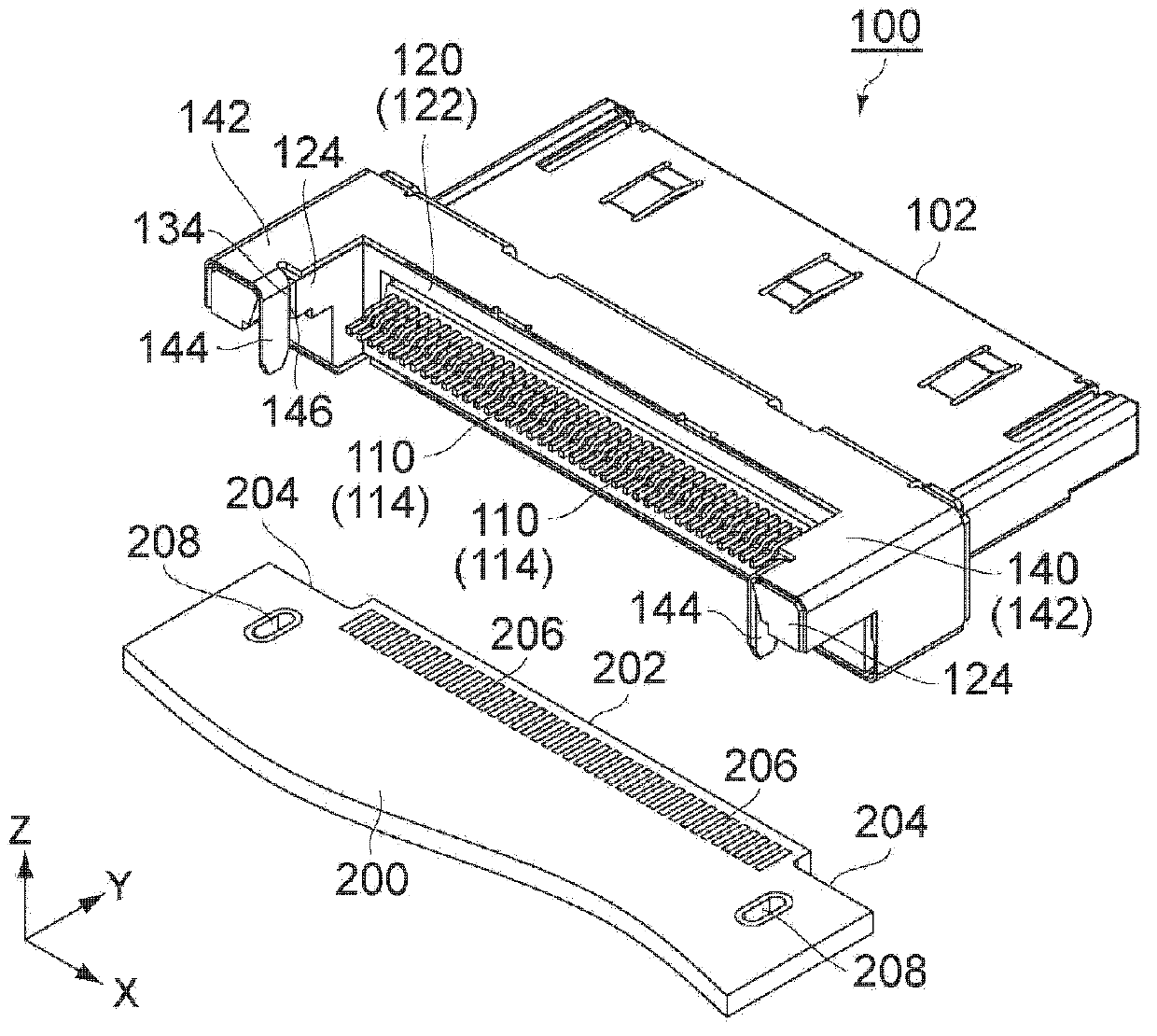
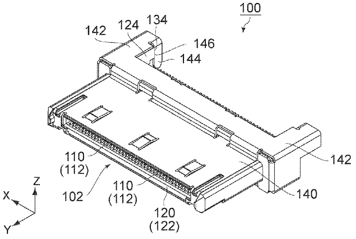
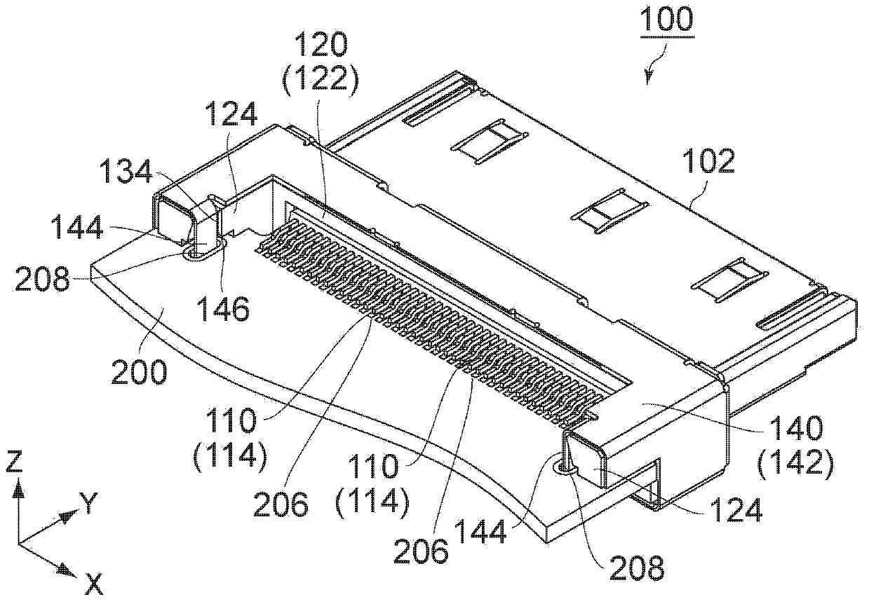
[0023] refer to figure 1 with image 3 , the connector 100 according to the first embodiment of the present invention is a plug connector. The connector 100 has a fitting portion 102 that is fitted with a fitting portion of a mating connector (receptacle connector: not shown). The fitting portion 102 is formed on the +Y (front) side of the connector 100 . In use, the connector 100 is mounted and fixed on the substrate 200 in a state where the fitting portion 102 protrudes in the +Y direction (forward) from the edge 202 of the substrate 200 . Such as figure 1 As shown, the substrate 200 is formed with two shoulders 204 . Each shoulder 204 is recessed from the edge 202 of the substrate 200 in the -Y direction (backward). A plurality of pads 206 are formed on the substrate 200 . A plurality of pads 206 are positioned proximate edge 202 and between shoulders 204 in the X direction (pitch direction). Two through holes 208 are formed on the substrate 200 . The through hole...

no. 2 example

[0038] refer to Figure 8 with Figure 9 , the connector 100A according to the second embodiment of the present invention is the connector 100 of the first embodiment (refer to figure 1 with image 3 ) modification example. The connector 100A of the second embodiment includes almost the same structure as the connector 100 of the first embodiment. Thus, in Figure 8 with Figure 9 In , the same reference numerals are given to components similar to those of the first embodiment, and therefore, detailed descriptions of these components will be omitted.

[0039] Such as Figure 8 with Figure 9 As shown, the connector 100A of the embodiment and the connector 100 (refer to figure 1 with image 3 ) differ only in the structural aspect of the housing fixing part. Therefore, the substrate 200A on which the connector 100A of the present embodiment is mounted is different from the substrate 200 of the first embodiment.

[0040] More specifically, as figure 1 with image ...


PUM


Abstract

Provided is a connector to be securely fixed on a board, especially, the connector having a high-strength shell prevented from detached from the connector. The connector has a mating portion, a plurality of the contacts, a holding member holding the contacts and a shell and to he connected with a mating connector in a front-back direction. The mating portion is positioned in forward part of the connector. The holding member is formed with a protrusive portion protruding back ward. The protrusive portion is formed with a receiving portion. An edge of the shell is formed a stopper portion. The stopper portion and the receiving portion face to each other in the front-back direction. The contact has a contact-fixing portion fixed on the board. The shell has a shell-fixing portion fixed on the board. A distance between the shell-fixing portion and the mating portion is larger than another distance between the contact-fixing portion and the mating portion.

Description

technical field [0001] The present invention relates to a connector configured to be mounted and fixed on a substrate in a state where a mating portion protrudes from an edge of the substrate. Background technique [0002] Connectors configured to be mounted on a substrate are disclosed, for example, in JP-A2007-5234, JP-B3817489, and JP-A2011-192409. These connectors are shown separately in the Figure 11 to Figure 12 middle. as in Figure 10 to Figure 12 As shown in , each connector has a housing formed by bending a blank member obtained by machining a sheet metal. The housing is connected to the holding member as follows. The housing is placed on the holding member from the front of the connector so as to cover the holding member. To form the stop, a part of the housing is bent. The stopper is in contact with the holding member, or the stopper is press-fitted into and held by the holding member. [0003] Each of the connectors disclosed in JP-A2007-5234 and JP-B3817...

Claims


Application Information

Patent Timeline
Patent Type & Authority Applications(China)
IPC IPC(8): H01R13/50H01R13/631
CPCH01R12/725H01R13/7039H01R13/6594
Inventor 木村雅纪横山阳平川濑浩司小寺真史
Owner JAPAN AVIATION ELECTRONICS IND LTD
Learn More