Cycloidal pin gear hydraulic pump
A cycloidal gear and hydraulic pump technology, which is applied in the field of hydraulic pumps, can solve problems such as high rotor precision requirements, difficult processing and manufacturing, and large fluctuations in working pressure, so as to eliminate the influence of oil pressure stability, simple structure, and easy drainage. The effect of volume increase
- Summary
- Abstract
- Description
- Claims
- Application Information
AI Technical Summary
Problems solved by technology
Method used
Image

Examples
Embodiment 1
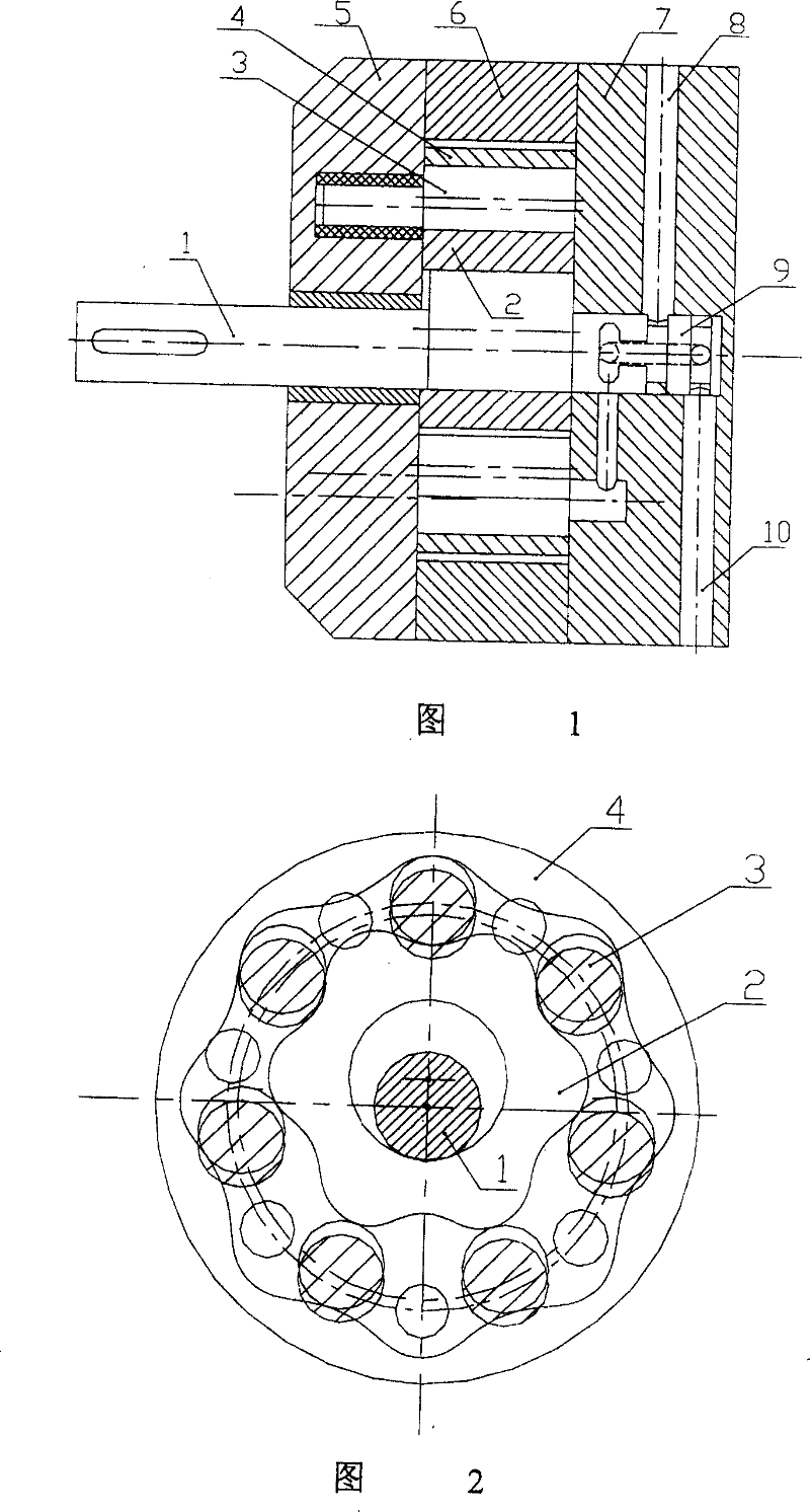
[0035] A needle-toothed cycloid gear hydraulic pump, the structure of which is shown in Figure 1. The hydraulic pump is mainly composed of a transmission shaft (1), an inner rotor (2), a needle tooth (3), a hypocycloid wheel (4), a front end cover (5), a pump body (6), a rear end cover (7), Liquid inlet (8), liquid outlet (10), flow distribution shaft (9) and other components. The transmission shaft (1) is an eccentric shaft, which drives the inner rotor (2) to rotate; the inner rotor (2) is a short epicycloid wheel or a circular wheel; the pin teeth (3) are eccentric pin teeth (3), and rotate eccentrically, The position of the rotation axis is fixed, and the rotation axis of the needle teeth (3) is distributed on a cylindrical surface with the rotation axis of the hypocycloid wheel (4) as the axis; the hypocycloid wheel (4) is a short hypocycloid ring gear, and the inner rotor (2) Set eccentrically with respect to the hypocycloid wheel (4); the inner rotor (2), the needle te...
Embodiment 2
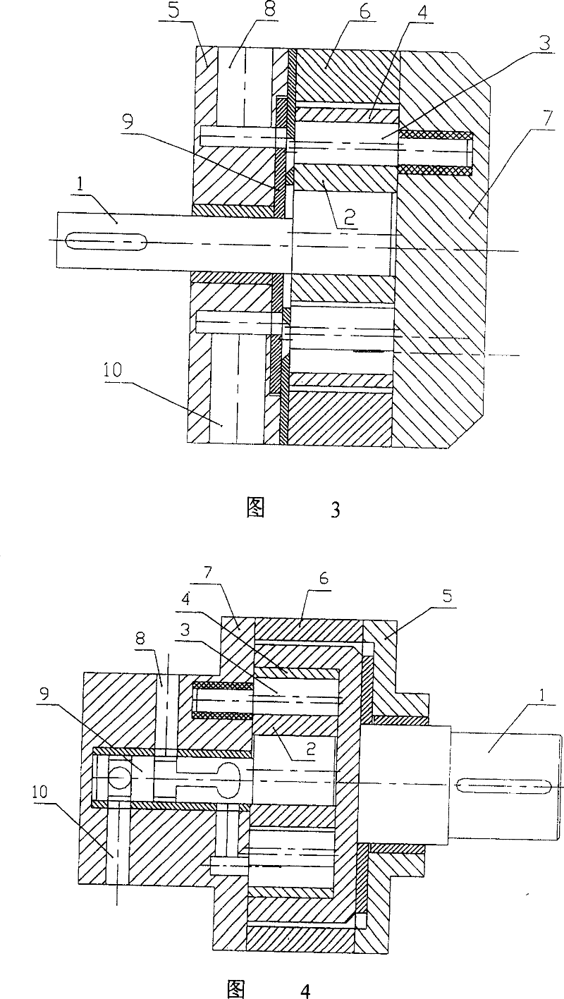
[0037]A needle cycloid gear hydraulic pump, the structure of which is shown in Figure 3. The hydraulic pump is mainly composed of transmission shaft (1), inner rotor (2), needle teeth (3), hypocycloid wheel (4), front end cover, pump body (6), rear end cover (7), liquid inlet (8), liquid outlet (10), distribution plate (9) and other components. The transmission shaft (1) is an eccentric shaft, which drives the inner rotor (2) to rotate; the inner rotor (2) is a circular wheel or a short epicycloidal wheel; the pin teeth (3) are eccentric pin teeth (3), and rotate eccentrically, The position of the rotation axis is fixed, and the rotation axis of the needle teeth (3) is distributed on a cylindrical surface with the rotation axis of the hypocycloid wheel (4) as the axis; the hypocycloid wheel (4) is a short hypocycloid ring gear, and the inner rotor (2) Set eccentrically with respect to the hypocycloid wheel (4); the inner rotor (2), the needle teeth (3), and the hypocycloid wh...
Embodiment 3
[0039] A needle-toothed cycloid gear hydraulic pump, the structure of which is shown in Figure 4. The hydraulic pump is mainly composed of transmission shaft (1), inner rotor (2), needle teeth (3), hypocycloid wheel (4), front end cover, pump body (6), rear end cover (7), liquid inlet (8), liquid outlet (10), flow distribution shaft (9) and other components. The transmission shaft (1) is fixedly connected with the hypocycloid wheel (4); the inner rotor (2) is a short epicycloid wheel or a disc; the pin teeth (3) are eccentric pin teeth (3), and rotate eccentrically, The axial position is fixed, and the rotation axis of the needle teeth (3) is distributed on the cylindrical surface with the rotation axis of the hypocycloid wheel (4) as the axis; the hypocycloid wheel (4) is a short hypocycloid ring gear, and the inner rotor ( 2) It is arranged eccentrically with respect to the hypocycloid wheel (4); the inner rotor (2), the needle teeth (3), and the hypocycloid wheel (4) form ...
PUM
 Abstract
Description
Claims
Application Information
 - R&D
- Intellectual Property
- Life Sciences
- Materials
- Tech Scout
- Unparalleled Data Quality
- Higher Quality Content
- 60% Fewer Hallucinations
Browse by: Latest US Patents, China's latest patents, Technical Efficacy Thesaurus, Application Domain, Technology Topic, Popular Technical Reports.
© 2025 PatSnap. All rights reserved.Legal|Privacy policy|Modern Slavery Act Transparency Statement|Sitemap|About US| Contact US: help@patsnap.com