Vacuum evaporation plating machine

An evaporation machine, vacuum technology, applied in the direction of vacuum evaporation plating, sputtering plating, ion implantation plating, etc., can solve the problems of difficult thin film, difficult vapor volume, etc., and achieve the effect of uniform evaporation

Inactive Publication Date: 2008-01-23
MITSUBISHI HEAVY IND LTD
View PDF6 Cites 0 Cited by
  • Summary
  • Abstract
  • Description
  • Claims
  • Application Information

AI Technical Summary

Problems solved by technology

Therefore, in the above method, even if the overall vapor amount can be controlled, it is difficult to control the vapor amount in the width direction of the relatively large FPD substrate, and it is difficult to obtain a uniform film by evaporation

Method used


Image

  • Vacuum evaporation plating machine
  • Vacuum evaporation plating machine
  • Vacuum evaporation plating machine

Examples


Embodiment 1

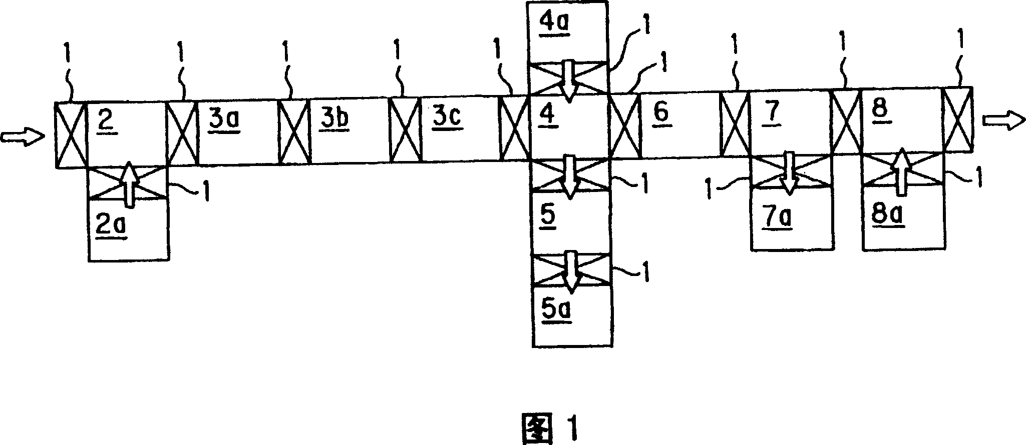
[0032] FIG. 1 is a schematic plan view showing an in-line film forming apparatus using a plurality of vacuum vapor deposition machines according to the present invention.

[0033] Hereinafter, as an example of an embodiment, the formation of an organic EL element of an FPD will be described as an example, but the vacuum vapor deposition machine of the present invention is not limited thereto, that is, it can be applied to the formation of other thin films on other substrates. In addition, the present invention is well suited for large substrates.

[0034] The in-line film forming apparatus shown in FIG. 1 is configured to form organic EL elements of FPDs in an in-line manner, and each processing chamber is provided with a gate door 1, and each processing chamber is provided with a different gate door. The process according to each purpose is carried out under the same vacuum condition.

[0035] Specifically, a glass substrate to be an FPD is conveyed from the left side in FIG...

Embodiment 2

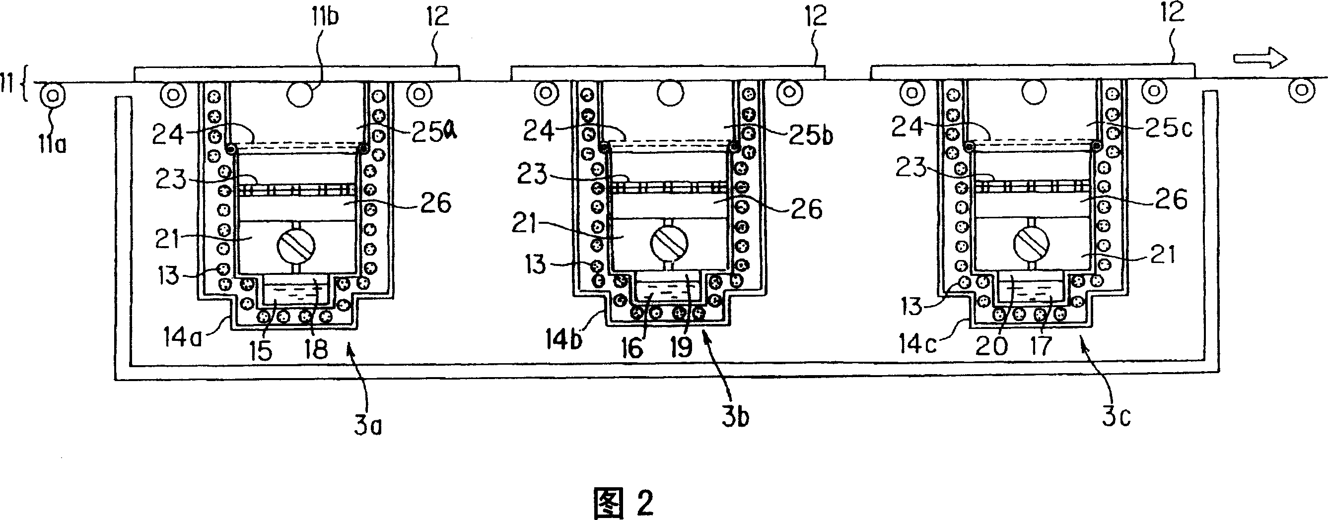
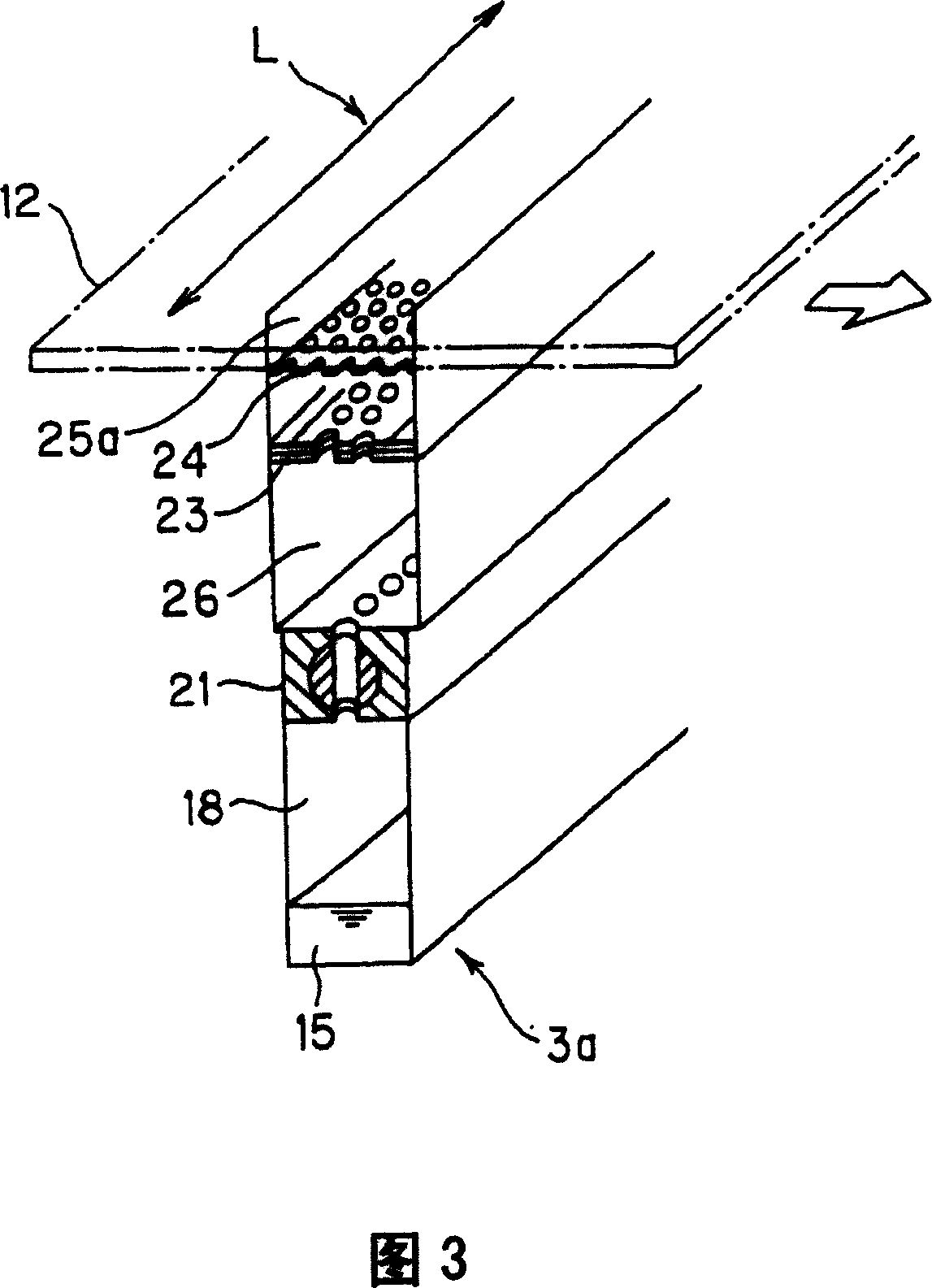
[0047] The valve member 21 is used to supply a uniform amount of vapor (concentration distribution) in the plate width direction L of the glass substrate 12, and the arrangement and direction of the flow path through which the vapor passes are not particularly limited as long as the same function can be achieved. Specifically, the valve member 21 has a structure in which, in order to uniformly supply the vapor amount of the vapor deposition material in the plate width direction L direction of the glass substrate, with respect to the vapor deposition chamber long in the plate width direction L direction, the plate A plurality of flow paths are provided in the direction of the width direction L, and the amount of steam passing through these flow paths can be independently controlled. Next, the mechanism and operation of the valve member 21 having the above structure will be described in detail with reference to FIG. 4 . In addition, FIG. 5 is a schematic diagram showing another ...

Embodiment 3

[0053] Fig. 5 (a) is a perspective view showing another embodiment of the valve part constituting the vacuum evaporation machine of the present invention; Fig. 5 (b), (c) is a B-B line view sectional view of Fig. 5 (a), and Indicates the operating status of the valve parts.

[0054]As shown in FIG. 5 , the valve member 21B includes at least a cuboid-shaped stopper member 41 having the length of the vapor-deposited region in the plate width direction L of the glass substrate 12 , and a cylindrical stopper member 41 provided inside the stopper member 41 in the longitudinal direction. The space portion of the cylindrical shape and the plurality of cylindrical shaft members 42 fitted in the cylindrical space portion. In the stopper member 41, an inlet hole 43 and an outlet hole 44 are formed at opposite positions, and when the communication hole 45 formed in the shaft member is arranged at a predetermined position, as shown in FIG. 5(b), for example, the communication hole 45 can ...


PUM


Abstract

Vapor deposition on a glass substrate 12 in the substrate width direction L is unified by providing a spool shutter 21 to uniformly control the quantity of the vapor of a vapor deposition material 15 flowing into the glass substrate 12 side from an evaporation chamber 18 side in the substrate width direction L of the glass substrate 12 and a perforated plate shutter 23 disposed on a lower side of the glass substrate 12 parallel to a surface to be vapor-deposited of the glass substrate 12 to rectify the in-plane distribution and the flow of the vapor of the vapor deposition material 15 in a vapor deposition chamber 25a in the vacuum vapor deposition machine. Thus, the a vacuum vapor deposition machine is capable of forming a uniform vapor flow of a vapor deposition material even in a large substrate, controlling the vapor distribution and unifying the vapor deposition.

Description

technical field [0001] The present invention relates to a vacuum vapor deposition machine for forming a thin film by vapor-depositing a vapor-deposition material on a vapor-deposited body such as a substrate. Background technique [0002] The so-called vacuum evaporation machine means that the evaporation material and the object to be evaporated are arranged in a vacuum container, and the evaporation material is heated and melted to evaporate or sublimate it to be vaporized in a state where the vacuum container is decompressed. A device that deposits vaporized evaporation material on the surface of the object to be evaporated to form a thin film. In the above-mentioned vacuum vapor deposition machine, as a method of heating the vapor deposition material, an external heating crucible method in which an external heater is used to heat the crucible in which the vapor deposition material is placed, or the like is being used. In recent years, the use of vacuum evaporation machin...

Claims


Application Information

Patent Timeline
Patent Type & Authority Patents(China)
IPC IPC(8): C23C14/24C23C14/54C23C14/56
CPCC23C14/54C23C14/24H10K71/164H10K71/00
Inventor 神川进森崎裕彦和田宏三平井悦郎小林敏郎加藤光雄平野龙也
Owner MITSUBISHI HEAVY IND LTD
Why Eureka
Try Eureka