Evaporator

A technology of evaporation machine and evaporation source, which is applied in the field of evaporation machine, can solve the problems of large consumption of film material and increase of coating cost, etc., and achieve the effect of improving utilization rate

Inactive Publication Date: 2014-04-23
HONG FU JIN PRECISION IND (SHENZHEN) CO LTD +1
View PDF7 Cites 0 Cited by
  • Summary
  • Abstract
  • Description
  • Claims
  • Application Information

AI Technical Summary

Problems solved by technology

When changing the material, in order to maintain the cleanliness of the film material, it is usually replaced with a new one, which consumes a lot of film material and increases the cost of coating

Method used


Image

  • Evaporator

Examples


Embodiment Construction

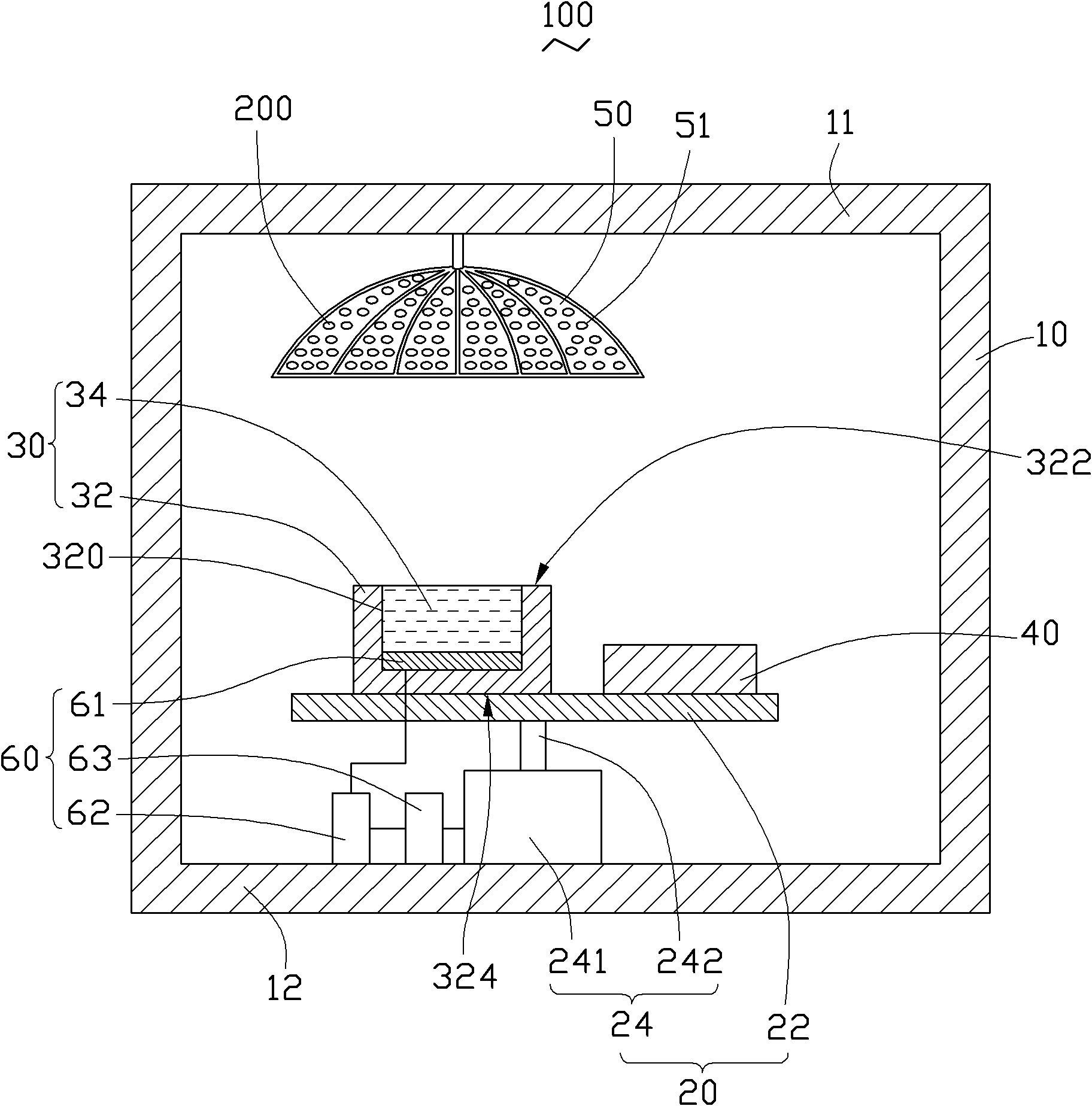
[0031] See figure 1 , The vapor deposition machine 100 provided by the present invention is used for vapor deposition of the substrate 200 to be coated. The evaporation machine 100 includes a cavity 10, a lifting drive assembly 20, a film material source 30, an evaporation source 40, a film coating umbrella stand 50, and a control device 60.

[0032] The cavity 10 is a hollow box which includes a top plate 11 and a bottom plate 12 opposite to the top plate 11.

[0033] The lifting drive assembly 20 is arranged on the bottom plate 12 of the cavity 10. The lifting drive assembly 20 includes a fixed plate 22 and a lifter 24. The fixing plate 22 is carried on the lifter 24 and can be raised and lowered relative to the bottom plate 12 under the drive of the lifter 24. Specifically, the lifter 24 includes a driving part 241 and a lifting part 242 that can be raised and lowered relative to the driving part 241. The driving part 241 is fixed on the bottom plate 12 of the cavity 10. Th...


PUM


Abstract

The invention discloses an evaporator, comprising a chamber, an ion emitting source, an evaporation source and a coated umbrella stand. The chamber comprises a top plate and a bottom plate opposite to the top plate. The coated umbrella stand is fixed on the inner side of the top plate of the chamber. The ion emitting source comprises a crucible holder and a membrane material. The crucible holder is provided with an accommodating tank for accommodating the membrane material. The evaporator further comprises a lifting driving assembly and a control device. The lifting driving assembly comprises a fixing plate and a lifter. The ion emitting source and the evaporation source are both fixed on the fixing plate. The fixing plate is connected to the lifter. The lifter is fixed on the bottom plate of the chamber and used for driving the fixing plate to life in relative to the bottom plate of the chamber. The control device is arranged in the chamber and electrically connected with the lifter and used for controlling the lifting height of the lifter, so that the distance between the membrane material in the accommodating tank and the coated umbrella stand always remains constant.

Description

Technical field [0001] The invention relates to an evaporation machine. Background technique [0002] The currently used vapor deposition machine mainly evaporates the film material through the electron beam, so that the material is deposited on the object to be plated. During the coating process, the following situations will occur: (1) When the electron beam continues to vaporize the film material, the position of the crucible in the evaporation chamber is fixed, and the film material in the crucible is relative to the height of the coating umbrella frame. It will be lower and lower, and the longer the evaporation time is, the greater the energy of the electron beam is required to maintain the same plating rate. Therefore, an additional electron beam power controller is required to control the power of the electron beam emitted electrons; 2) When the height of the film material in the crucible becomes lower and lower, the electron beam may not have enough energy to evaporate t...

Claims


Application Information

Patent Timeline
Patent Type & Authority Patents(China)
IPC IPC(8): C23C14/30
Inventor 廖名扬吴佳颖
Owner HONG FU JIN PRECISION IND (SHENZHEN) CO LTD
Why Eureka
Try Eureka