OLED evaporation crucible

A crucible and evaporation technology, applied in vacuum evaporation coating, sputtering coating, ion implantation coating and other directions, can solve the problem of blocking the nozzle, save heat consumption, avoid condensation and block the nozzle, and the structure is simple. Effect

Pending Publication Date: 2018-07-03
JIANGYIN GUANGKE PHOTOELECTRIC PRECISION EQUIP CO LTD
View PDF0 Cites 0 Cited by
  • Summary
  • Abstract
  • Description
  • Claims
  • Application Information

AI Technical Summary

Problems solved by technology

[0003] The purpose of the present invention is to overcome the defects in the prior art, provide OLED evaporation crucible, realize that the nozzle of the nozzle is always at a relatively high temperature, and avoid the condensation of the evaporation steam when passing through the nozzle and block the nozzle. Happening

Method used


Image

  • OLED evaporation crucible
  • OLED evaporation crucible
  • OLED evaporation crucible

Examples


Embodiment 1

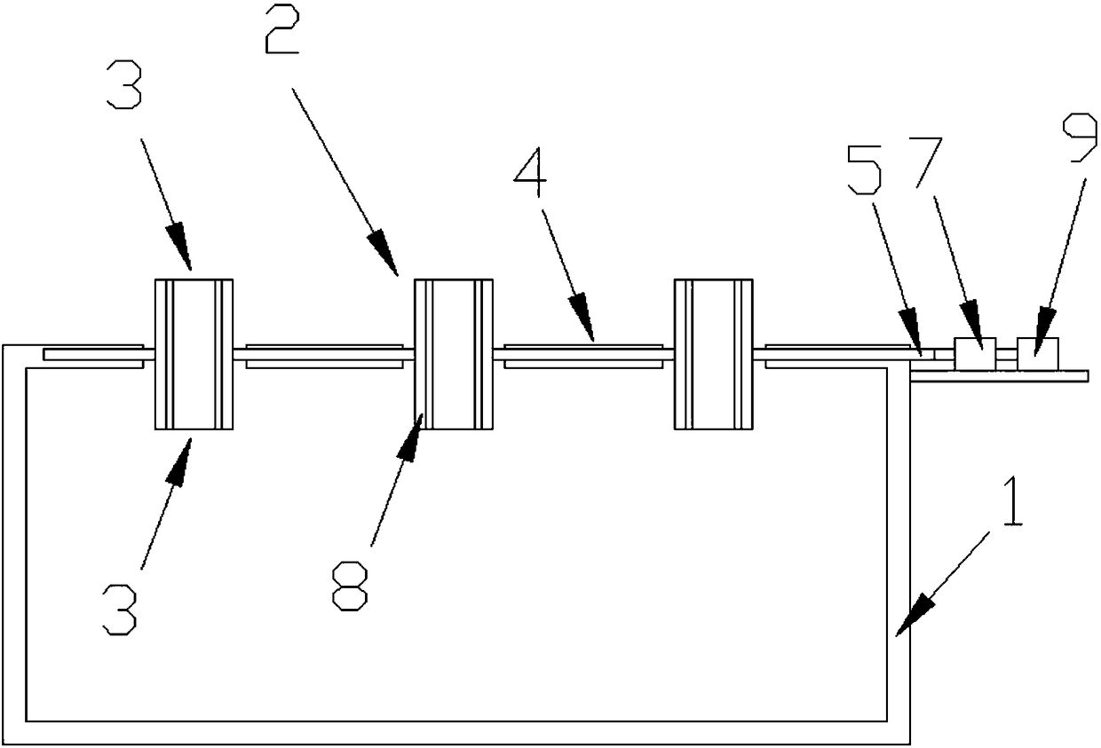
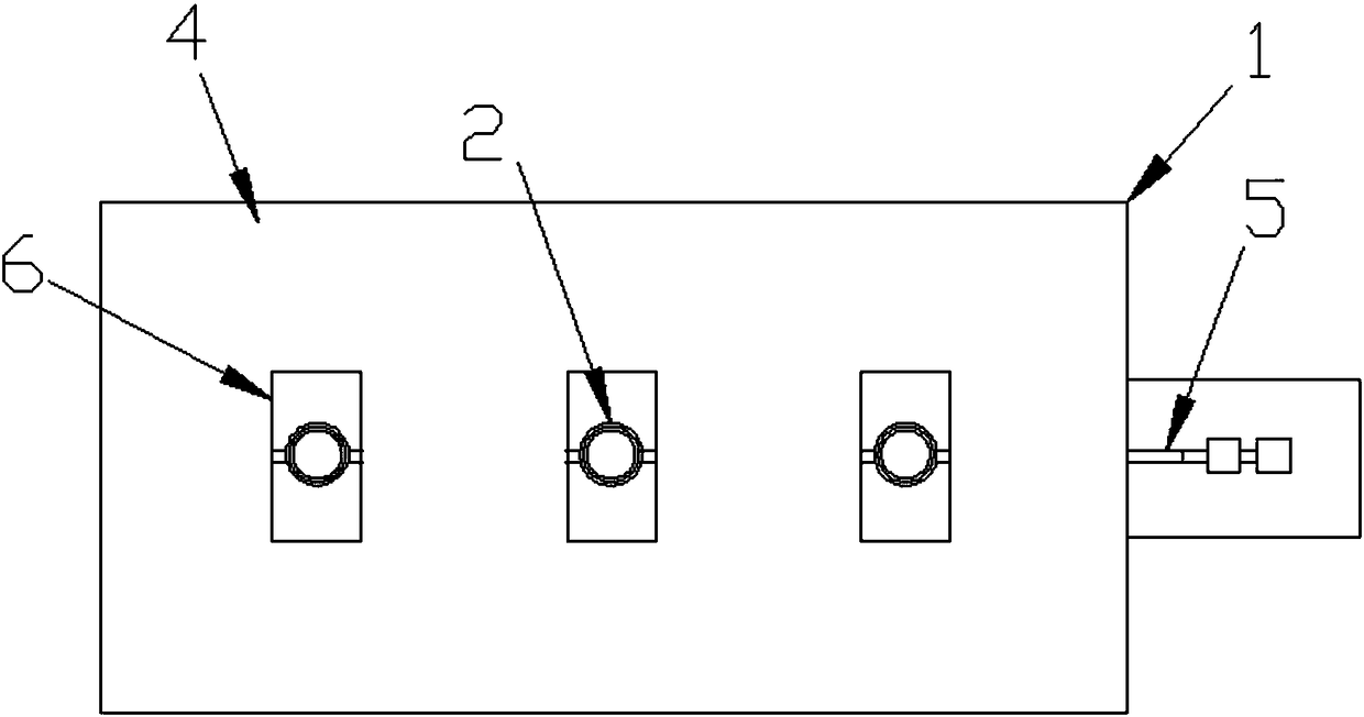
[0023] Such as figure 1 , figure 2 As shown, the present invention is an OLED evaporation crucible, including a crucible body 1 and an evaporation vapor ejection structure 2 provided on the crucible body 1, and the evaporation vapor ejection structure 2 includes a spout 3 for ejection or overflow of the evaporation vapor , The vapor deposition steam ejection structure 2 is provided with an anti-spout clogging mechanism. The evaporation steam ejection structure 2 is a tubular nozzle, and the nozzle 3 is the two ports of the nozzle. The anti-spout blocking mechanism includes a rotating shaft 5 that is installed in the top plate 4 of the crucible body 1, and several nozzles are fixedly connected to the rotating shaft 5, adjacent to each other. The nozzles are arranged at intervals, all the nozzles are placed at the same position on the rotating shaft 5, the axis of the rotating shaft 5 is set perpendicular to the axis of the nozzle, the rotating shaft 5 is fixedly connected to ...

Embodiment 2

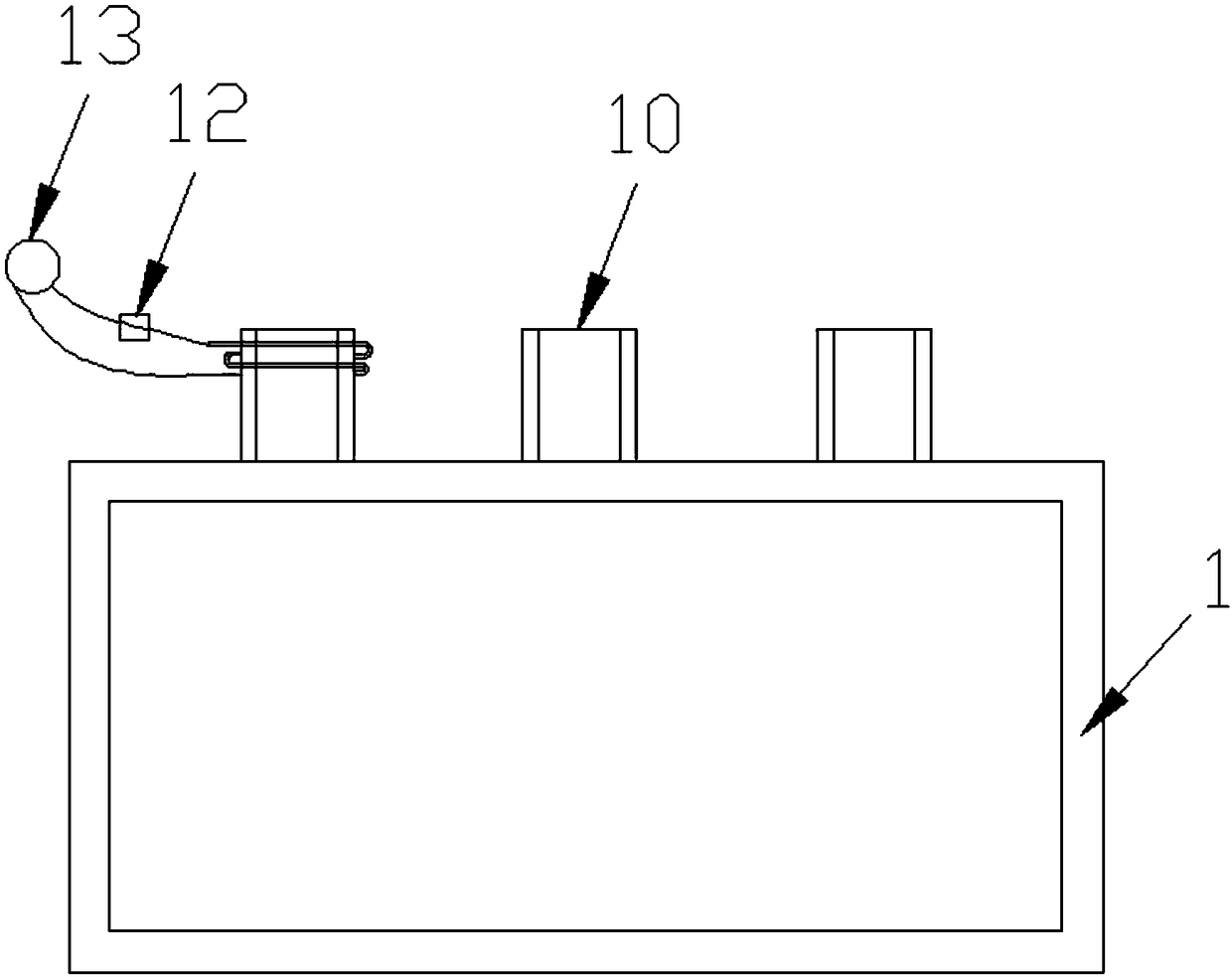
[0025] The difference from Embodiment 1 is that, as image 3 , Figure 4 shown (for ease of illustration, image 3 Not all coils are shown), the vapor deposition steam ejection structure 2 is a steel pipe 10 fixedly connected to the top plate 4 of the crucible body 1, one end of the steel pipe 10 communicates with the inner cavity of the crucible body 1, and the other end is ejected or overflowed as vapor deposition steam A coil 11 is wound around the outer peripheral surface of the steel pipe 10, and the coil 11 is connected to a power source 13 through a voltage regulator 12. The coil 11 is covered with a magnetic and heat insulating layer 14. Several steel pipes 10 are provided to form multiple spouts 3, the steel pipe 10 located in the middle of the crucible body 1 is a straight pipe, and the remaining steel pipes 10 are bent pipes.

Embodiment 3

[0027] The difference from Embodiment 1 is that, as Figure 5 to Figure 8 shown (for ease of illustration, Figure 5 The through hole 16 and the electromagnet 20 are not shown; Figure 6 The side plate of the crucible body is not shown), the vapor deposition steam ejection structure includes a spout for ejection or overflow of the vapor deposition vapor, and the vapor deposition vapor ejection structure includes a cover hole that is rotatably arranged on the lower surface of the top plate 4 of the crucible body Plate 15, the hole-shielding plate 15 is a rectangular plate, the top plate 4 on the crucible body is a rectangular plate with a size larger than the hole-shielding plate 15, the nozzle is a through hole 16 arranged on the top plate 4 on the crucible body, and a corner of the hole-shielding plate 15 is set through The lower surface of the upper top plate 4 of the crucible body is fixedly provided with a shaft 17 adapted to the aforementioned hole, and the hole-shieldin...


PUM


Abstract

The invention discloses an OLED evaporation crucible. The OLED evaporation crucible comprises a crucible body and an evaporation steam blowing-off structure arranged on the crucible body, wherein theevaporation steam blowing-off structure comprises a nozzle used for blowing off or overflowing evaporation steam, and a mechanism used for preventing the nozzle from being blocked is arranged on the evaporation steam blowing-off structure. The OLED evaporation crucible has the advantages that the nozzle is rotatably arranged, and cooling rate at the nozzle is reduced, so that an opening of the nozzle is always at a relatively high temperature by only controlling the rotating speed of a rotating shaft in the whole evaporation process, and the conditions that the evaporation steam is condensed when passing through the nozzle and the opening is blocked are avoided; or the nozzle adopts a steel pipe, and an eddy current way is combined, so that temperature of the steel pipe at the opening reaches the temperature which can prevent the evaporation steam from being condensed at the opening, and the conditions that the evaporation steam is condensed when passing through the nozzle and the opening is blocked are also avoided.

Description

technical field [0001] The invention relates to an OLED evaporation crucible. Background technique [0002] OLED stands for Organic Light-Emitting Diode (Organic Light-Emitting Diode), also known as Organic Electroluminesence Display (OLED). Because of its lightness, lightness, power saving and other characteristics, it has been widely used in the display screen of digital products, and has great market potential. At present, the application of OLED in the world is focused on flat panel display, because OLED is a The only technology that can be compared with TFT-LCD in terms of application, OLED is the only display technology among all current display technologies that can produce large-size, high-brightness, high-resolution soft screens, and can be made into the same thickness as paper; Among them, In the OLED production process, the vacuum coating process is a very important process in the OLED production process. Vacuum coating refers to heating and evaporating the evapo...

Claims


Application Information

Patent Timeline
Patent Type & Authority Applications(China)
IPC IPC(8): C23C14/24
CPCC23C14/243
Inventor 瞿建强瞿一涛黄仕强陆彬锋
Owner JIANGYIN GUANGKE PHOTOELECTRIC PRECISION EQUIP CO LTD
Why Eureka
Try Eureka