Fume emission continuous monitoring method and system

A flue gas emission and monitoring system technology, applied in measurement devices, material analysis by optical means, instruments, etc., can solve the problems of damage to the gas chamber gas pipeline, not being heated by an electric heating device, and temperature drop, etc., to reduce Corrosion, maintainability and stability, slow cooling effect

Active Publication Date: 2009-03-18
FOCUSED PHOTONICS +1
View PDF1 Cites 23 Cited by
  • Summary
  • Abstract
  • Description
  • Claims
  • Application Information

AI Technical Summary

Problems solved by technology

[0009] When the above monitoring system suddenly loses power during the working process, there will be residual gas in the gas chamber, which is not heated by the electric heating device, and the temperature will drop; the water vapor in the residual gas will condense, and some acidic gases in the gas will dissolve in Condensed water, such as sulfur dioxide and nitrogen oxides, thus forming highly corrosive acids, corroding and damaging gas chambers and gas pipelines and other devices

Method used


Image

  • Fume emission continuous monitoring method and system
  • Fume emission continuous monitoring method and system
  • Fume emission continuous monitoring method and system

Examples


Embodiment 1

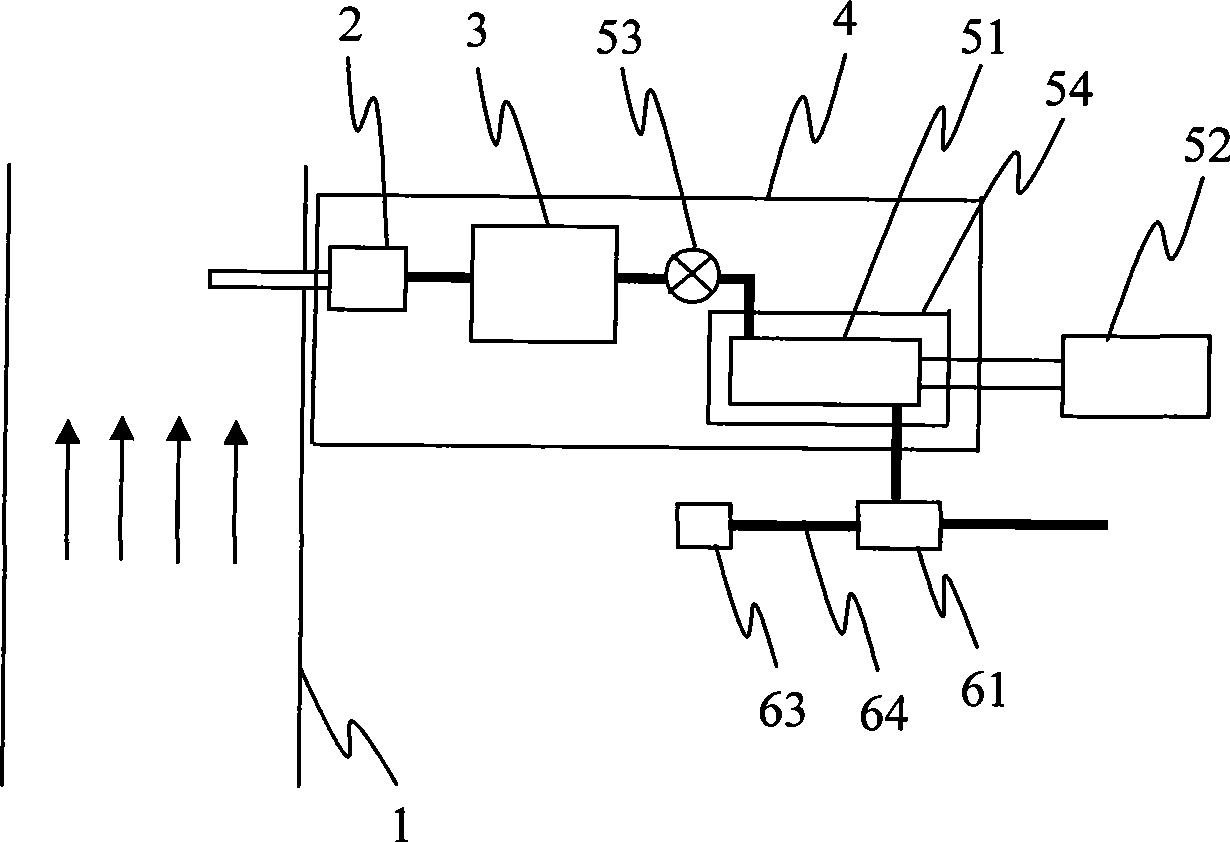
[0041] Such as figure 1 As shown, a continuous monitoring system for flue gas emission includes a flow path heating device 4, a measuring device 52, a sequentially connected sampling device 2, a pretreatment device 3, a valve 53, a gas chamber 51 and a jet device, wherein the sampling The device 2 , the pretreatment device 3 , the valve 53 and the gas chamber 51 are arranged in the flow path heating device 4 .

[0042] The sampling device 2 is installed on the flue 1 , and the measuring device 52 is connected with the gas chamber 51 .

[0043] The gas chamber 51 is set in the heat preservation device 54, and the inlet end of the gas chamber 51 is provided with a valve 53, which is opened when the power is turned on, so that the sampled flue gas can pass into the gas chamber 51, and is closed when the power is turned off.

[0044] The jet device provides power to sample the flue gas from the flue, and also plays the role of displacing the flue gas in the gas chamber after a po...

Embodiment 2

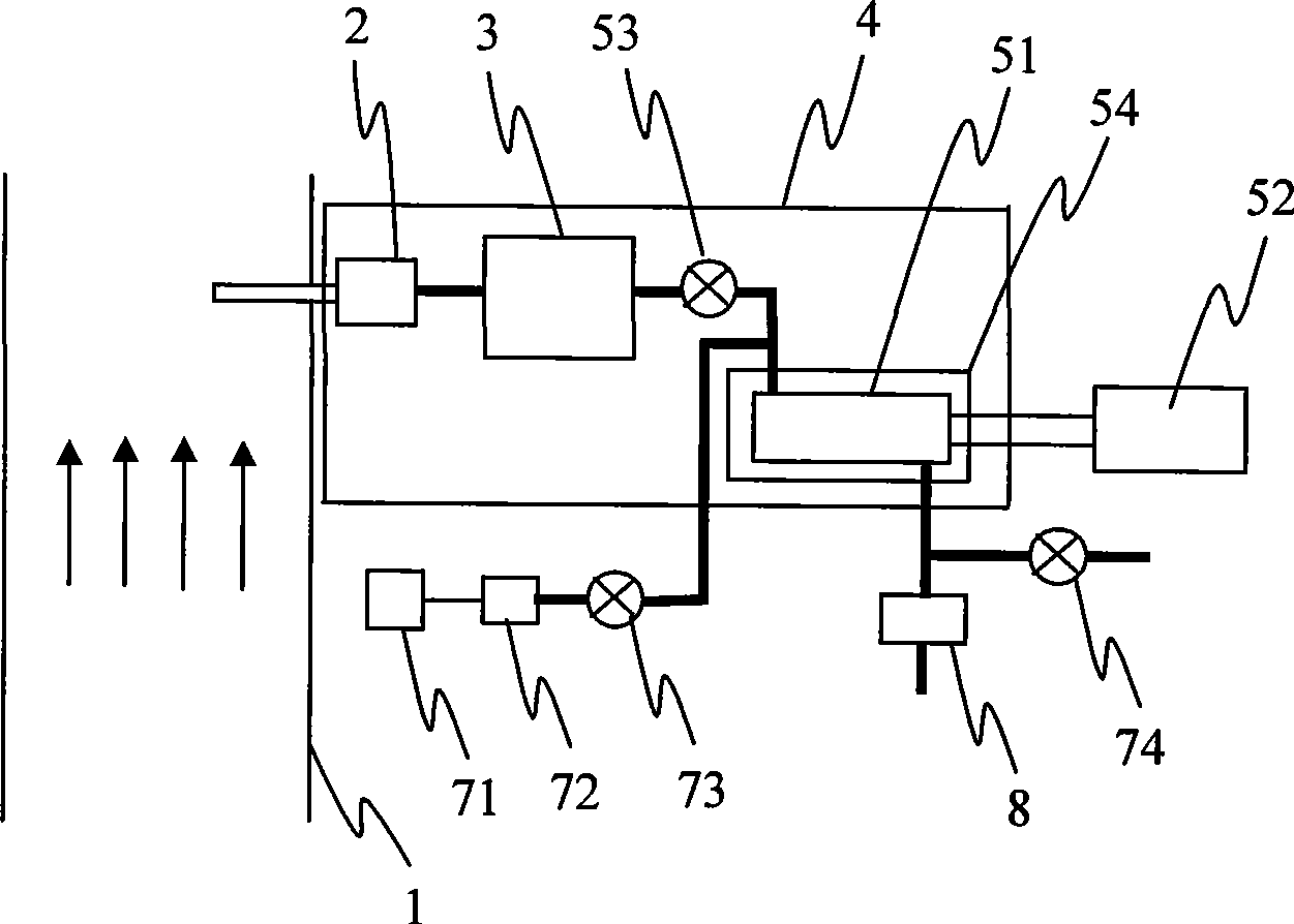
[0057] Such as figure 2 Shown, a kind of flue gas emission continuous monitoring system is different from embodiment 1:

[0058] 1. Use an ordinary air pump 8 to replace the jet device.

[0059] 2. The gas replacement device includes a gas source 71, a filter device 72, valves 73, 74, the gas source 71, filter device 72 and valve 73 connected in sequence are arranged at the inlet end of the gas chamber 51, and the valve 74 is arranged at the end of the gas chamber 51. export port. Valves 73, 74 are closed when energized and opened when de-energized.

[0060] This embodiment also discloses a method for continuous monitoring of flue gas emissions, which is different from Embodiment 1 in that:

[0061] When energized, the exhaust pump 8 works to extract the flue gas in the flue 1 for measurement.

[0062] When the system is powered off, the air pump 8 stops working and disconnects the communication between the gas chamber 51 and the outside world. At this moment, the valves 7...

Embodiment 3

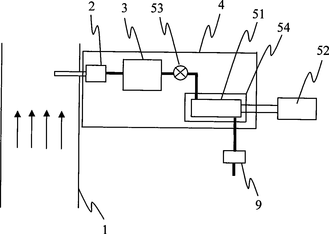
[0065] Such as image 3 Shown, a kind of flue gas emission continuous monitoring system is different from embodiment 2:

[0066] Remove the gas source 71, filter device 72, valves 73, 74, and set a diaphragm pump 9 at the outlet of the gas chamber 51 that still communicates the gas chamber 51 with the outside world when the power is cut off.

[0067] This embodiment also discloses a method for continuous monitoring of flue gas emissions, which is different from Embodiment 2 in that:

[0068] When energized, the diaphragm pump 9 works to extract the flue gas in the flue 1 for measurement.

[0069] When the system is powered off, the diaphragm pump 9 stops working, but the gas chamber 51 is still communicated with the outside world. At this time, the residual gas in the gas chamber 51 is slowly replaced with the clean air (without corrosive components and little moisture content) from the outside. During the replacement process, the heat preservation device 54 ensures that the...


PUM


Abstract

The invention discloses a smoke discharge continuous monitoring method, comprising the steps that: a, sampling device works to continuously sample the smoke in a smoke pipeline; b, the valve at the inlet of the gas chamber is opened to transmit the sampled smoke into the gas chamber; c, a measurer measures the parameters of the smoke in the gas chamber, and in power off, the valve at the inlet of the gas chamber is closed, the clean gas without corrosive components and much water is exchanged with the residue gas in the gas chamber. The invention further discloses a smoke discharge continuous monitoring system. The invention has the advantages that the smoke discharge continuous monitoring method and the smoke discharge continuous monitoring system can prevent corroding and damage the gas chamber, polluting the gas chamber and blocking the gas pipeline, having simple structure, maintainability, stability and wide application in smoke discharge continuous monitoring.

Description

technical field [0001] The invention relates to a continuous monitoring method and system for flue gas discharge, which is applied to the continuous monitoring of flue gas discharge, especially when the monitoring system is applied to the situation where the environmental power supply is unstable. Background technique [0002] In order to effectively monitor the emission of pollutants from pollution sources, the continuous emission monitoring system (CEMS) is currently used to measure the concentration of harmful gases in the flue, the flow rate of flue gas, the humidity of flue gas and other parameters, and the measured The parameters are sent to the environmental monitoring department so that corresponding countermeasures can be taken according to the measured parameters. [0003] US Patent No. 5,621,213 discloses a continuous monitoring system for flue gas emissions, including a sampling device installed on the flue, a pretreatment device, a gas chamber, a jet pump, and a...

Claims


Application Information

Patent Timeline
Patent Type & Authority Applications(China)
IPC IPC(8): G01N21/00G01N1/24G01N35/00
Inventor 韩双来李增珍王健
Owner FOCUSED PHOTONICS
Why Eureka
Try Eureka