A Heavy Oil Cold Recovery Technology Applicable to Shallow Well Formation
A heavy oil and process technology, applied in the field of heavy oil extraction devices, can solve the problems of difficult packer manufacturing, high packer requirements, and reduced viscosity of heavy oil, etc., to achieve safe and reliable production, realize fluidity, improve The effect of efficiency
- Summary
- Abstract
- Description
- Claims
- Application Information
AI Technical Summary
Problems solved by technology
Method used
Image
Examples
Embodiment 1
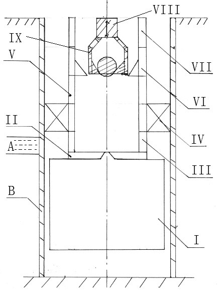
[0028] Embodiment 1, with reference to attached figure 1 , a heavy oil cold recovery device suitable for shallow well formation mentioned in the present invention, its technical scheme is: comprising packer IV, oil well pump VI, oil pipe VII, oil production layer A, oil well casing B, the oil well casing In the pipe B, the oil pipe VII is fixed through the packer IV. The oil well pump VI is installed in the oil pipe VII. The packer IV is located on the upper side of the oil production layer A. The improvement is: it also includes the gas generator I, the reaction opener II, Hydraulic switch III and reversing bypass valve V, the lower side wall of the oil well pump VI of the oil pipe VII is provided with a reversing bypass valve V, and the bottom of the oil pipe VII is connected to the gas generator through the hydraulic switch III and the reaction opener II I, the hydraulic switch III corresponds to the oil production layer A, the gas generator I is in the lower part of the oi...
Embodiment 2
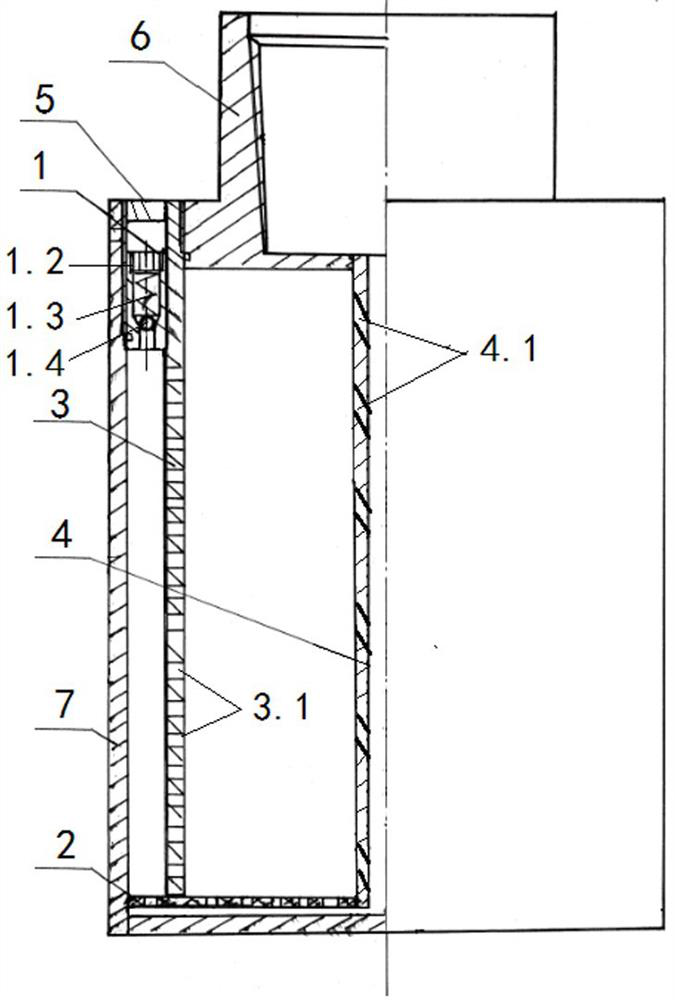
[0047] Embodiment 2, with reference to accompanying drawing, the difference between the present invention and embodiment 1 is:
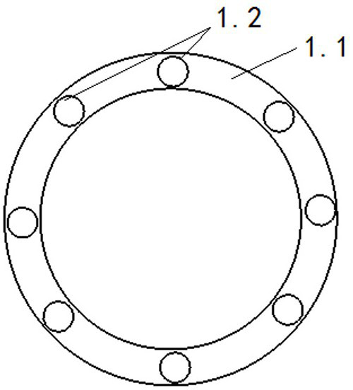
[0048] The gas generator 1 of the present invention comprises a reaction rate limiter 1, an exhaust plate 2, a chemical reactor 3, a reaction drip pipe 4, an air outlet directional plate 5, a butt joint 6, and a gas collector 7, and the upper part of the gas collector 7 is provided with There is a butt joint 6, and the inner cavity of the gas collector 7 is provided with a chemical reactor 3, and the inner cavity of the chemical reactor 3 is equipped with CaC 2 , the bottom of the chemical reactor 3 is provided with an exhaust plate 2, and the upper part of the annular cavity formed between the chemical reactor 3 and the gas collector 7 is provided with a reaction speed limiter 1, and the water entering the reaction drip pipe 4 from the butt joint 6 Water enters the chemical reactor 3 through the bottom, and with the CaC in the chemical reactor 3 2 ...
PUM
 Abstract
Description
Claims
Application Information
 - R&D
- Intellectual Property
- Life Sciences
- Materials
- Tech Scout
- Unparalleled Data Quality
- Higher Quality Content
- 60% Fewer Hallucinations
Browse by: Latest US Patents, China's latest patents, Technical Efficacy Thesaurus, Application Domain, Technology Topic, Popular Technical Reports.
© 2025 PatSnap. All rights reserved.Legal|Privacy policy|Modern Slavery Act Transparency Statement|Sitemap|About US| Contact US: help@patsnap.com


