HVAC desiccant wheel system and method

a desiccant wheel and desiccant technology, applied in the field of hvac systems, can solve the problems of current systems that often fail to address these efficiency concerns and current systems with desiccant wheels often disregard a critical period

Inactive Publication Date: 2007-07-19
TRANE INT INC
View PDF16 Cites 23 Cited by
  • Summary
  • Abstract
  • Description
  • Claims
  • Application Information

AI Technical Summary

Benefits of technology

[0022]One or more of these and/or other objects of the invention are provided by an HVAC system that includes a desiccant wheel, wherein the configuration and/o...

Problems solved by technology

Current systems often fail to address these efficiency concerns.
Moreover, current systems wit...

Method used


Image

  • HVAC desiccant wheel system and method
  • HVAC desiccant wheel system and method
  • HVAC desiccant wheel system and method

Examples


Embodiment Construction

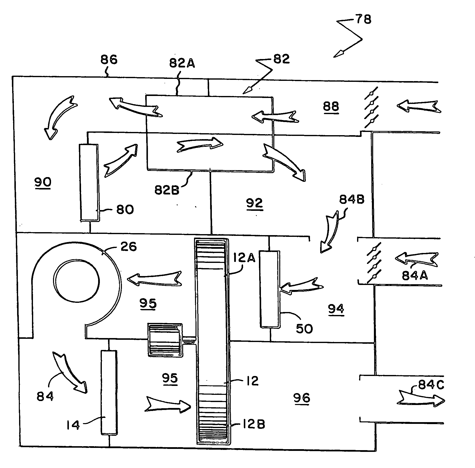
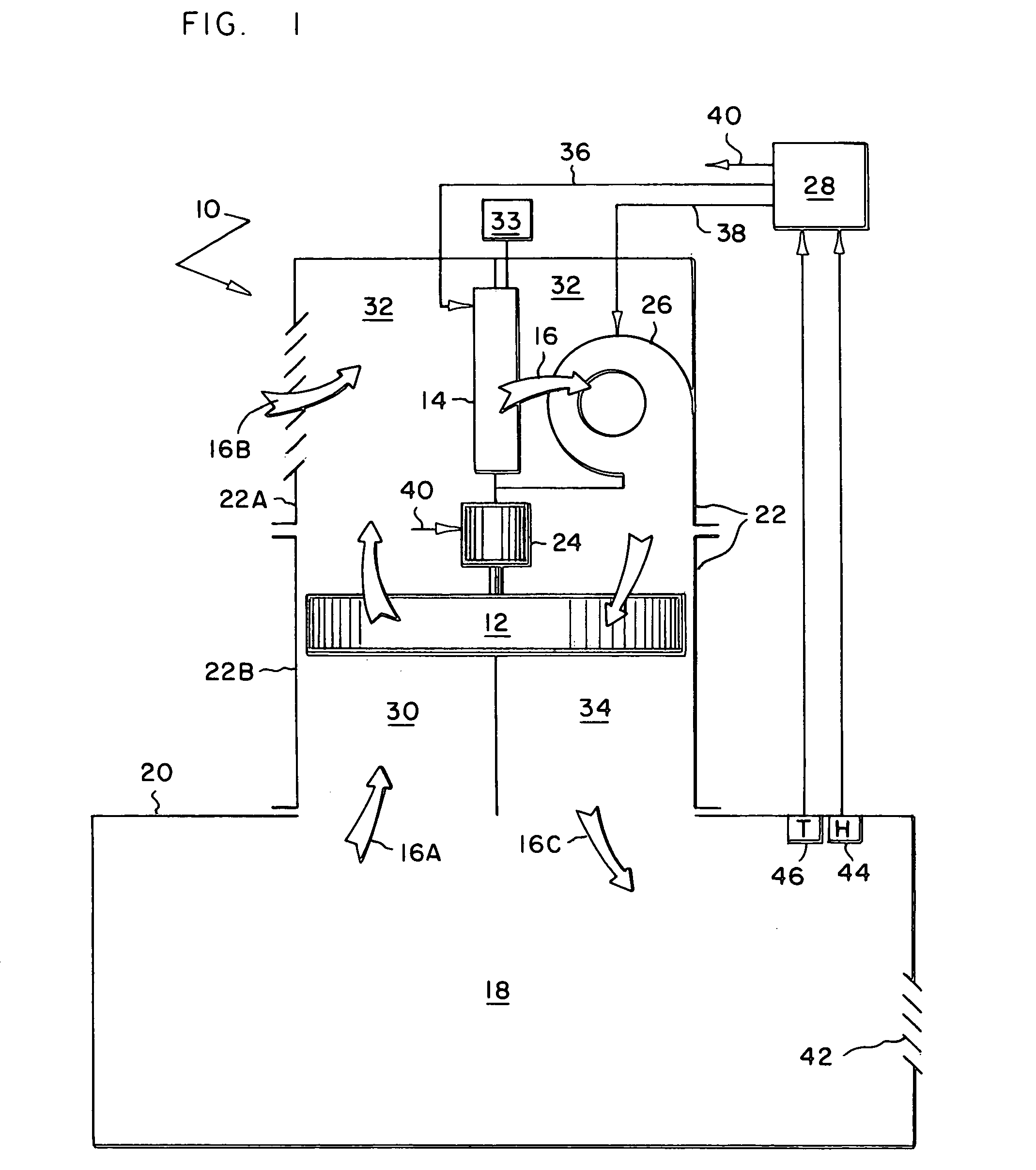
[0027]A refrigerant system 10, shown in FIG. 1, is cycled on and off to meet a latent and / or sensible cooling demand, wherein a desiccant wheel 12 of the system operates for at least a predetermined period at the beginning of each cycle. At the start of each cycle, it can take a moment for a cooling coil 14, such as an evaporator of a refrigerant circuit, to become sufficiently cool to condense moisture from the air 16. Moisture, which may have condensed on the surface of coil 14 during an earlier operating cycle, may later evaporate back into the air upon starting a new cycle. So, operating wheel 12 for a predetermined period at startup can help absorb that moisture before it raises the humidity of a comfort zone 18, such as a room or other area of a building 20.

[0028]For the illustrated embodiment, system 10 comprises an enclosure 22 that contains cooling coil 14, desiccant wheel 12 driven by a motor 24, a blower 26, and a controller 28.

[0029]Enclosure 22 is schematically illustra...


PUM


Abstract

An HVAC system includes a desiccant wheel, wherein the wheel's speed varies with airflow, the wheel is energized for at least a set period at startup, and/or a heat recovery system (e.g., an air-to-air heat exchanger) upstream of the wheel enhances the system's ability to dehumidify air.

Description

BACKGROUND OF THE INVENTION [0001]1. Field of the Invention[0002]The subject invention generally pertains to HVAC systems and more specifically to an air conditioning system that includes a dehumidifying desiccant wheel.[0003]2. Description of Related Art[0004]Energy wheels and desiccant wheels are two distinct types of wheels used in the HVAC industry. An energy wheel is a rotating, porous mass that functions as heat exchanger by transferring sensible heat from one air stream to another. With an energy wheel, half the wheel absorbs heat while the other half releases it. Examples of energy wheels are disclosed in U.S. Pat. Nos. 6,141,979 and 4,825,936.[0005]Desiccant wheels, on the other hand, transfer moisture from one air stream to another, usually for the purpose of reducing humidity of a comfort zone. Examples of systems with desiccant wheels are disclosed in U.S. Pat. Nos. 6,311,511; 6,237,354; 5,887,784; 5,816,065; 5,732,562; 5,579,647; 5,551,245; 5,517,828 and 4,719,761.[0006...

Claims


Application Information

Patent Timeline
IPC IPC(8): F25D17/06F25D17/04F25D23/00
CPCF24F3/1423F24F2203/1004F24F2203/1016F24F2203/1084F24F2203/104F24F2203/1068F24F2203/1032
Inventor MOFFITT, RONNIE R.
Owner TRANE INT INC
Why Eureka
Try Eureka