Reciprocating steel pipe drawer

The technology of a reciprocating and extubating machine is applied in the field of steel rolling equipment, which can solve the problems of low work efficiency, large equipment and large driving force.

Inactive Publication Date: 2008-02-06
王剑波 +1
View PDF8 Cites 0 Cited by
  • Summary
  • Abstract
  • Description
  • Claims
  • Application Information

AI Technical Summary

Problems solved by technology

The disadvantages of this kind of equipment are: 1. The equipment is huge, the structure is complex, the equipment cost is high, and it requires a large driving force, which greatly increases the manufacturing cost of the steel pipe; 2. The work efficiency is low, and only one stroke is effective for drawing steel pipes. The second pulling can only be done after the car returns

Method used


Image

  • Reciprocating steel pipe drawer
  • Reciprocating steel pipe drawer

Examples


Embodiment Construction

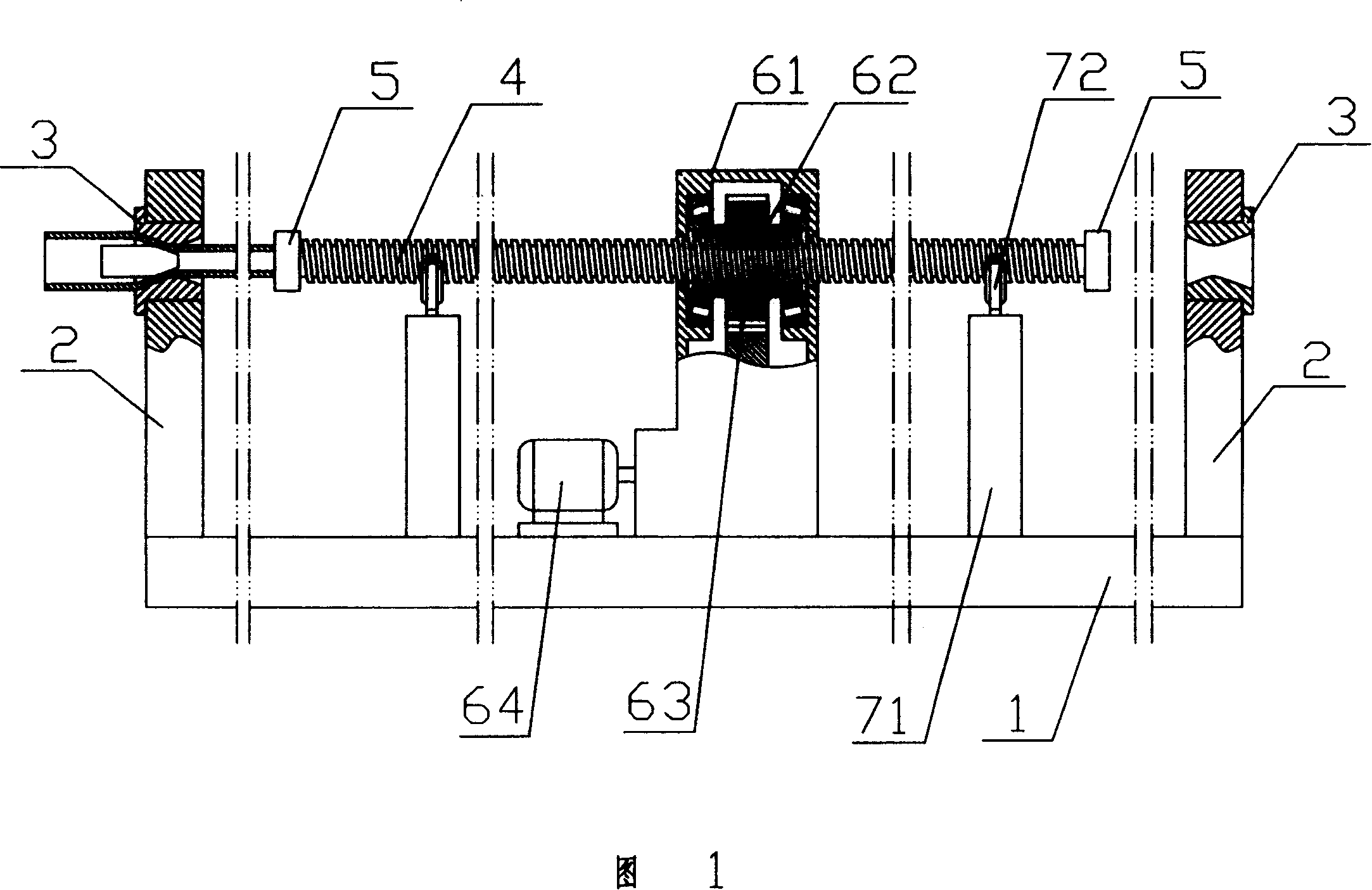
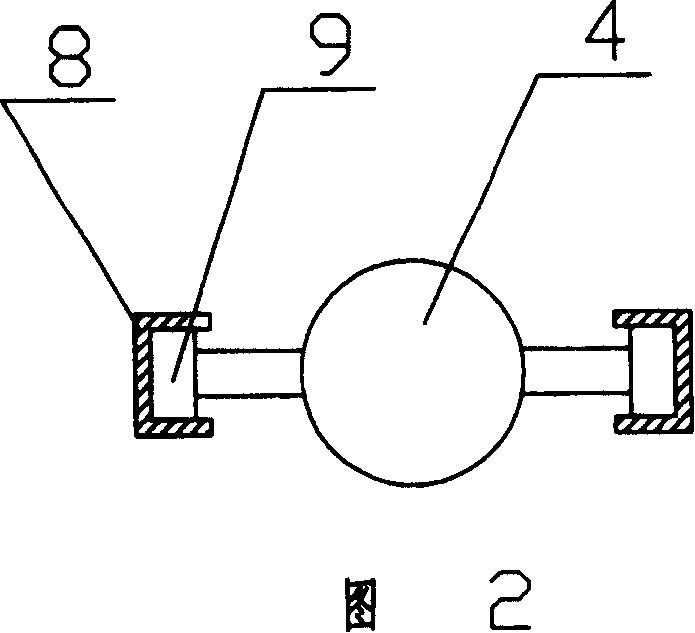
[0011] As shown in accompanying drawing 1, the reciprocating steel pipe pulling machine comprises a frame 1, and the two ends of the frame 1 are respectively equipped with a reducing die support 2, and a reducing die 3 is installed on the reducing die support 2, which are located at two ends. Between the reducing die brackets 2 there is an extruding screw 4 that can move left and right along the centerlines of the two reducing dies 3, and steel pipe clamps 5 are respectively installed at both ends of the extubating leading screw 4, which are located on the two reducing die supports 2 The extubation screw driving device is installed on the frame 1 in the middle position.

[0012] The extubation screw driving device includes a gearbox housing 61, a nut 62 installed in the gearbox housing 61 and matched with the extubation screw 4, and a drive gear 63 fixedly connected to the nut 62, passing through the middle The gear drives the motor 64 that drives the gear 63 to rotate, and th...


PUM


Abstract

A reciprocating steel pipe drawing machine is composed of machine frame, reducing dies and their supporters at both ends of machine frame, screw bolt between said reducing dies for drawing steel pipe and its driver, and steel pipe clamps installed to both ends of said screw bolt. It features its bidirectional drawing for high productivity.

Description

technical field [0001] The invention relates to a steel rolling equipment, in particular to a steel pipe pulling machine. Background technique [0002] Existing steel pipe extubation machine is mainly made up of extubation vehicle, and the crawler belt that drives extubation vehicle movement and extubation die, pulls pipe by extubation vehicle and completes extubation through extubation die. The disadvantages of this kind of equipment are: 1. The equipment is huge, the structure is complex, the equipment cost is high, and it requires a large driving force, which greatly increases the manufacturing cost of the steel pipe; The second pull can only be carried out after the car returns. Contents of the invention [0003] The technical problem to be solved by the present invention is to provide a reciprocating steel pipe pulling machine which has a simple structure and can continuously pull steel pipes. [0004] In order to achieve the above object, the technical solution of ...

Claims


Application Information

Patent Timeline
Patent Type & Authority Patents(China)
IPC IPC(8): B21C1/22
Inventor 罗宁
Owner 王剑波
Why Eureka
Try Eureka