Needle protector for cylindrical sewing machine

A sewing machine, straight cylinder type technology, applied in the direction of needle holders for sewing machines, sewing machine components, sewing equipment, etc., can solve problems such as failure to improve production efficiency, shaking of sewing needles, broken needles or skipped stitches, etc.

Inactive Publication Date: 2008-02-06
SHING RAY SEWING MACHINE
View PDF9 Cites 0 Cited by
  • Summary
  • Abstract
  • Description
  • Claims
  • Application Information

AI Technical Summary

Problems solved by technology

[0003] Since industrial sewing machines are required to achieve the function of high-efficiency production, it is inevitable to achieve this function with high sewing speed and reduce the probability of needle breakage. Existing sewing machines all use high-speed motors to speed up sewing. However, although high-speed motors are used It will increase the speed, but the sewing needle will vibrate under high-speed motion. Due to the fast needle feeding speed and the shaking of the sewing needle, the chance of needle breakage will increase. Therefore, it is necessary to interrupt the sewing work, causing trouble. Can't increase productivity
[0004] The needle retainer mechanism (see Fig. 1) of the existing straight cylinder sewing machine is to connect the front retainer needle 13a on the lower looper 40, and with the shaft rod 41 of the lower looper 40 being controlled to move, when the sewing needle (not shown in the figure) after the needle is advanced downwards, and when preparing to lift the needle upwards, the lower looper 40 starts to move at this time, and is ready to pass through the looped yarn (not shown in the figure), and then drives the front retaining needle 13a to approach The back stop needle 12a; and the back stop needle 12a is connected to the cloth pushing tooth 42, and the cloth pushing tooth 42 is driven by the connecting rod 43, and then pushes the back stop needle 12a close to the front stop needle 13a, and slightly clamps the sewing needle, However, this needle stop mechanism clamps the sewing needle when the sewing needle is about to start lifting upwards, and its front and rear stop needles 13a, 12a are driven by different shaft rods 41 and connecting rods 43 respectively. If the timing is not well grasped, it is easy to cause broken needles or skipped needles

Method used


Image

  • Needle protector for cylindrical sewing machine
  • Needle protector for cylindrical sewing machine
  • Needle protector for cylindrical sewing machine

Examples


Embodiment Construction

[0017] Relevant detailed description and technical contents of the present invention are as follows now in conjunction with the accompanying drawings:

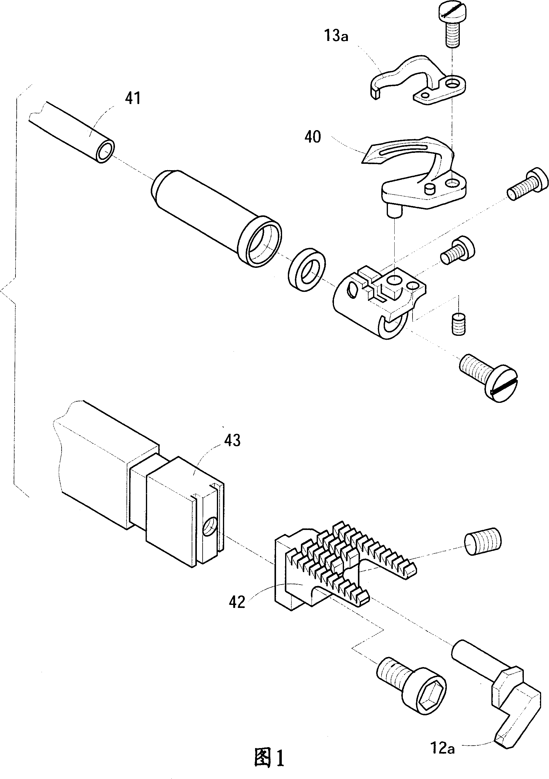
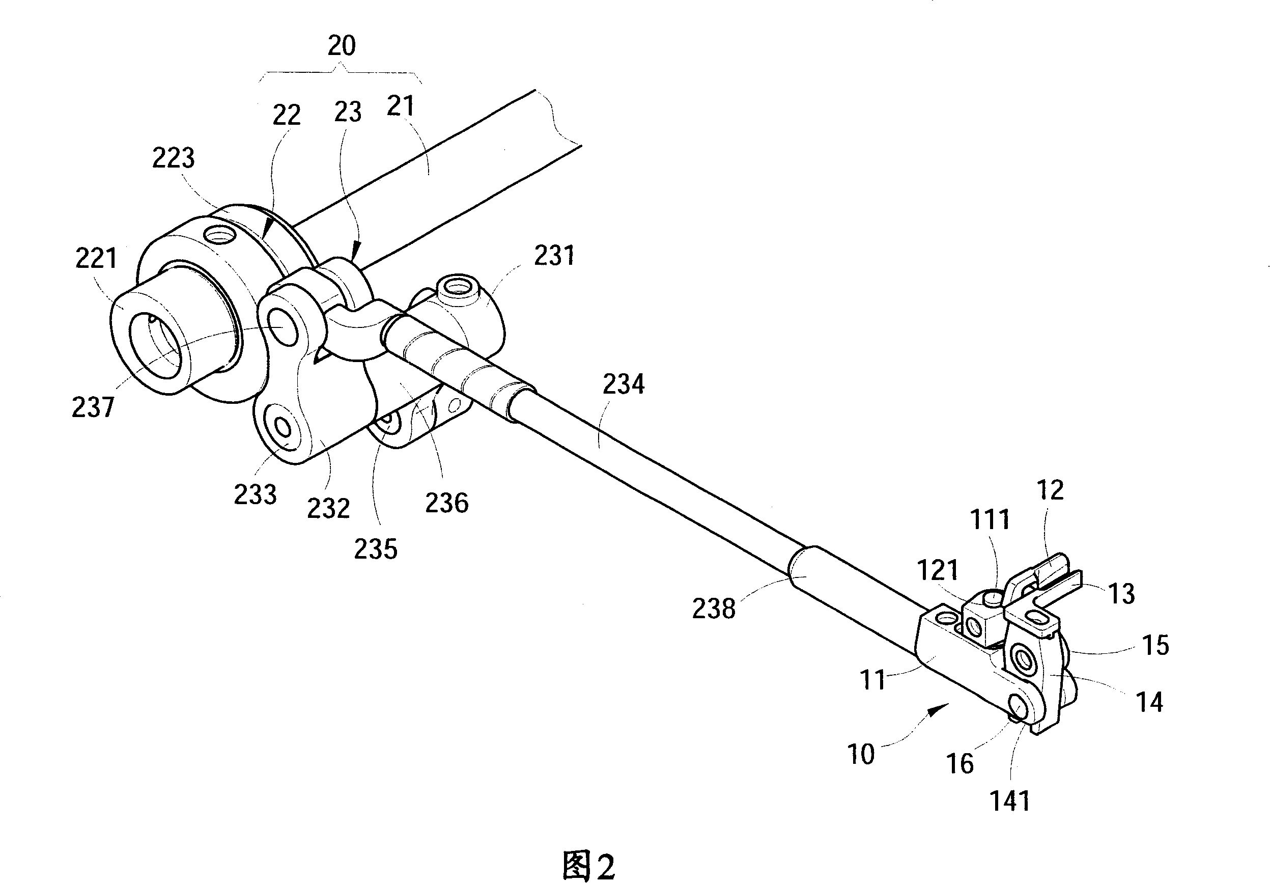
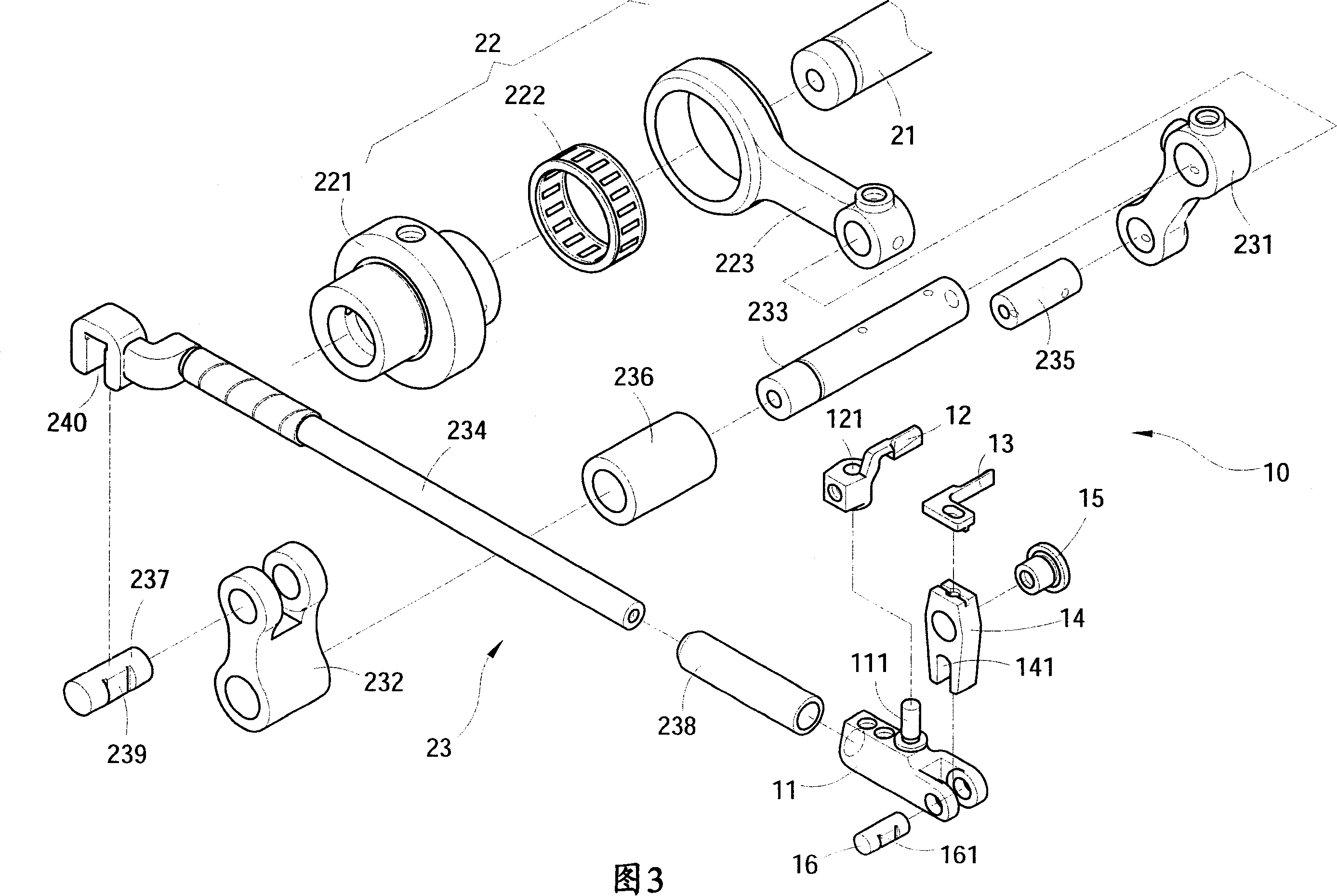
[0018] Please refer to Figures 2 and 7, the needle stop mechanism is placed inside the sewing table of the sewing machine 1. When the sewing needle 30 goes down to the sewing table, the needle stop mechanism can stabilize the shaking machine due to high-speed movement. The sewing needle 30 includes a needle stopper 10 and a transmission mechanism 20. The needle stopper 10 includes a movable body 11, a rear stopper 12, and a front stopper 13. The rear stopper 12 is connected to the top of the movable body 11, and The front pin 13 straddles the front end of the top of the movable body 11, and can do reciprocating swinging motion; and the transmission mechanism 20 includes a rotating main shaft 21, a steering mechanism 22, and a linkage mechanism 23, and the rotating main shaft 21 provides a rotational force, and It is connected ...


PUM


Abstract

This invention discloses a structure of warding needle in a straight barrel-type sewing machine. It is used to stabilize the vehicle sewing needle when the needle reaches downward the sewing pedestal in order to get rid of the swinging of the needle that may lead to cracking or jumping. In addition, the structure of the warding needle can adjust the time difference when the warding needle is forward and backward. This invention includes a device of warding the needle and a driving mechanism. The device consists of a moving body and forward and back needles, the forward needle is fixed on the moving body while the back needle is designed over the body. When the driving mechanism offers a force that drives the moving body of the warding needle repeatedly, the warding needle will oscillate against the above-mentioned movements, when the vehicle sewing needle is matched downward, it will close to the back warding needle to stabilize the swinging sewing needle.

Description

technical field [0001] The invention relates to a needle retaining mechanism of a straight cylinder sewing machine, in particular to a needle retaining mechanism of a straight cylinder sewing machine which stabilizes sewing needles shaking due to high-speed movement when the sewing machine is in use. Background technique [0002] The sewing industry technology has reached a fairly sophisticated stage. Now there are more fast and easy sewing machines for the mass production of garments in factories. The early sewing machines were manually operated one by one with feet and manual operations. Most of the sewing factories today Fully automatic operation is used to assist manual labor, so as to achieve the purpose of increasing production efficiency and reducing costs. [0003] Since industrial sewing machines are required to achieve the function of high-efficiency production, it is inevitable to achieve this function with high sewing speed and reduce the probability of needle br...

Claims


Application Information

Patent Timeline
Patent Type & Authority Patents(China)
IPC IPC(8): D05B55/06
Inventor 卓瑞荣
Owner SHING RAY SEWING MACHINE
Why Eureka
Try Eureka