Yarn Winder

A winding device, a technology for sliver, used in transportation and packaging, folding thin materials, transporting filamentous materials, etc.

Inactive Publication Date: 2008-02-20
TSTM CO LTD
View PDF3 Cites 0 Cited by
  • Summary
  • Abstract
  • Description
  • Claims
  • Application Information

AI Technical Summary

Problems solved by technology

[0004] The present invention is used to solve the problems caused by the above-mentioned conventional sliver winding devices, and its purpose is to provide a coil width that can be obtained even if the free lengths (fri-legs) of adjacent traverse devices are different. Sliver take-up for substantially uniform packages

Method used


Image

  • Yarn Winder
  • Yarn Winder
  • Yarn Winder

Examples


Embodiment Construction

[0035] Hereinafter, the present invention will be described in detail with reference to the drawings illustrating a first embodiment of the present invention.

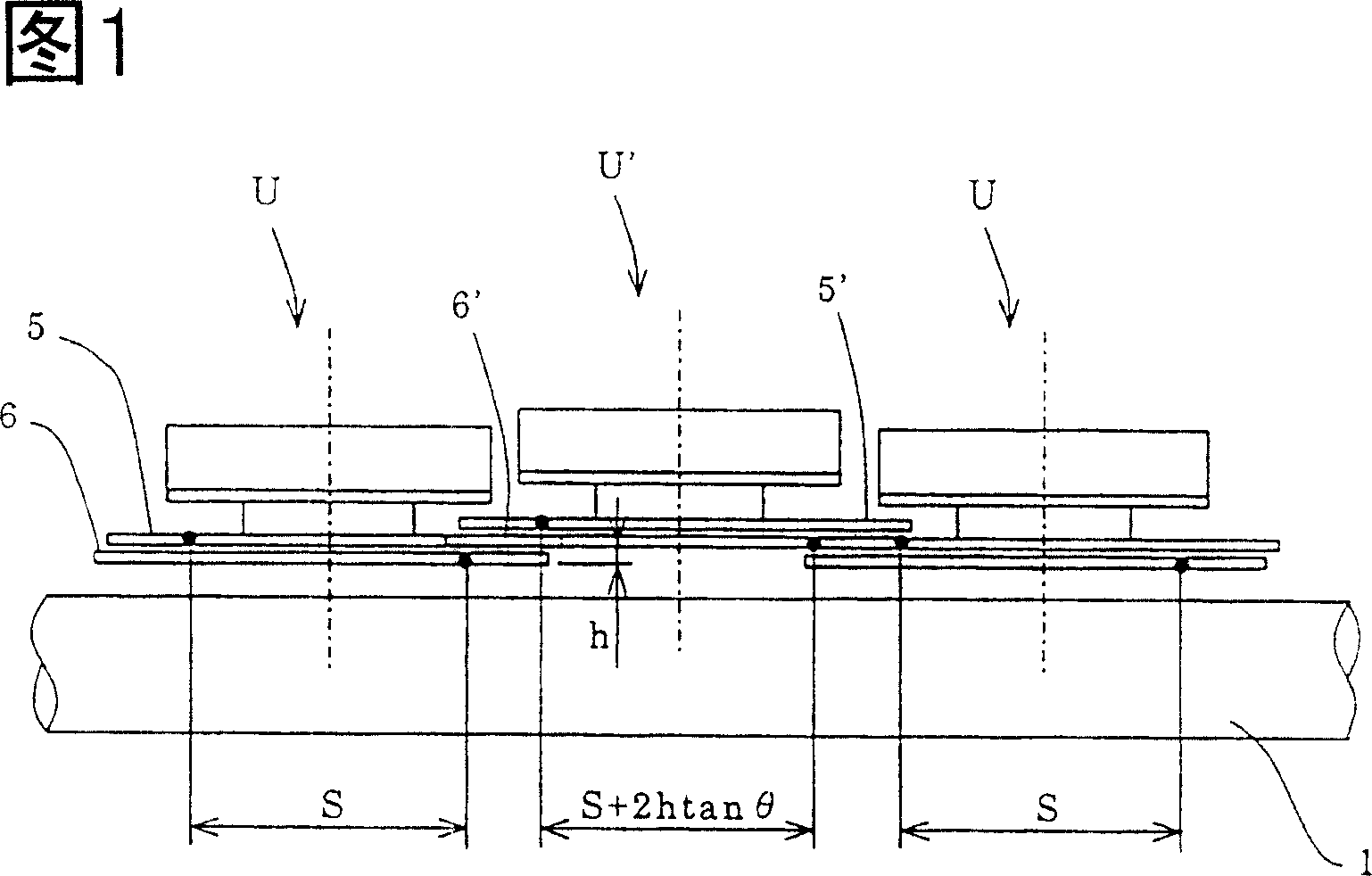
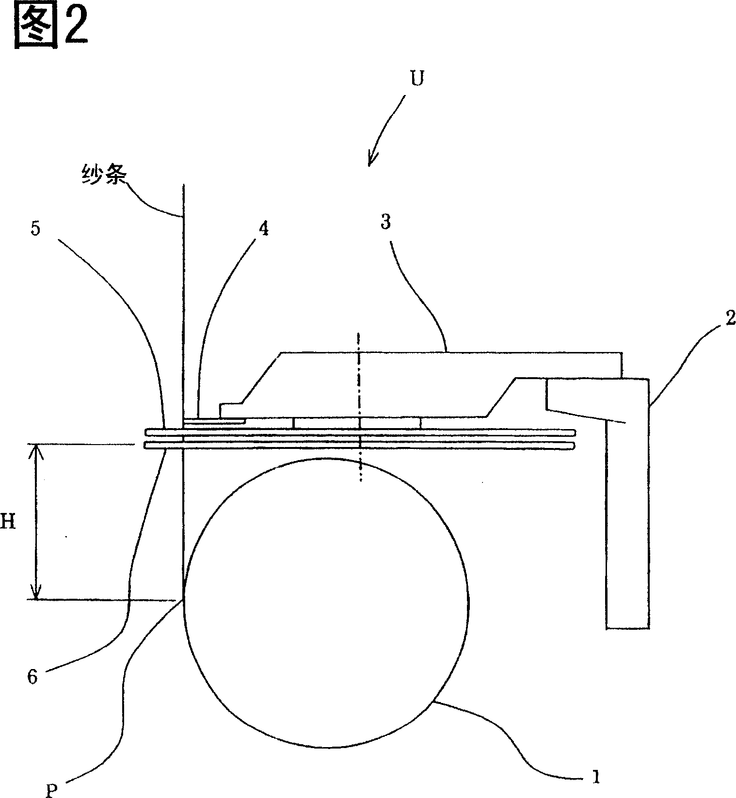
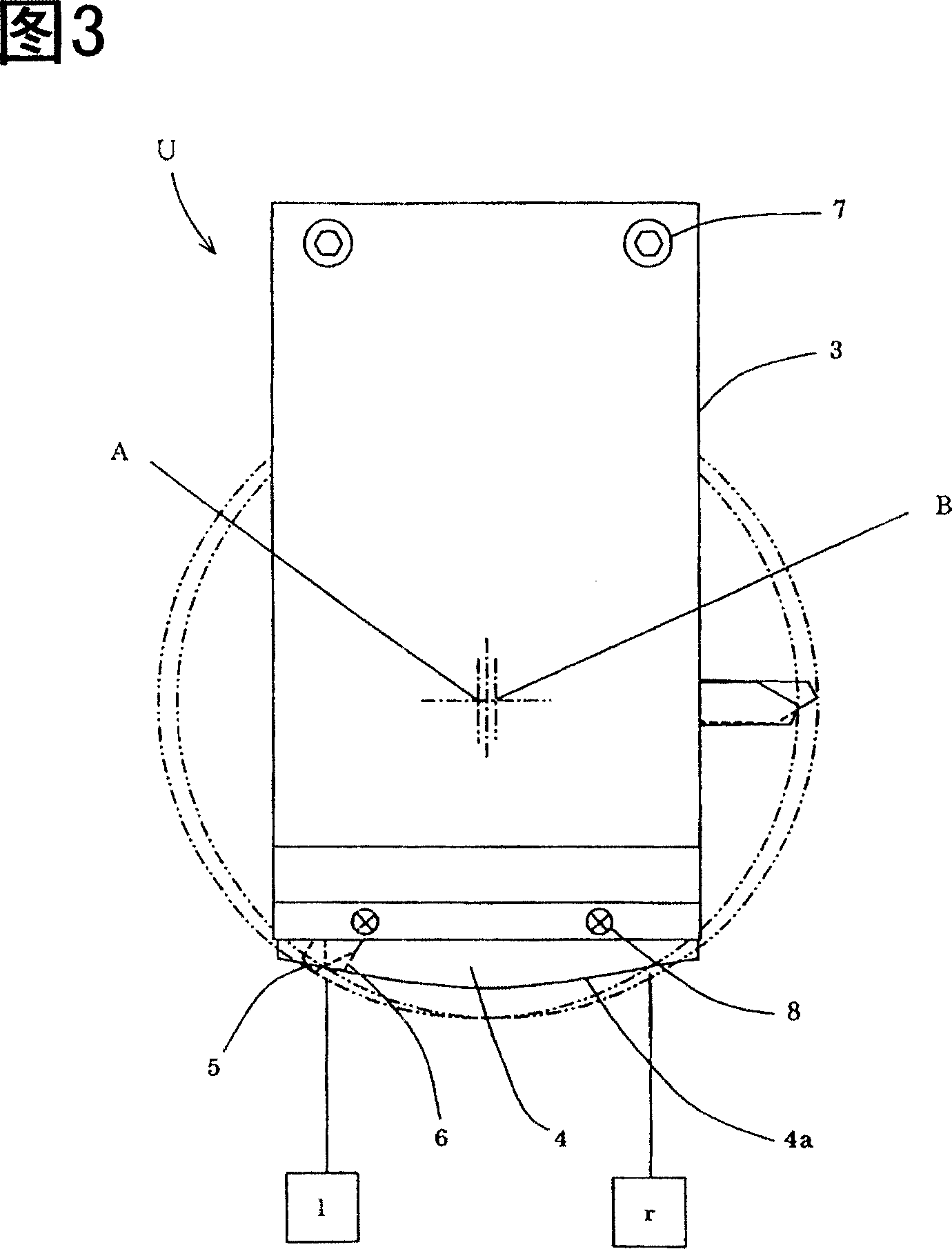
[0036] Fig. 1 is a front view of a first embodiment of the present invention. FIG. 2 is a side view of FIG. 1 . FIG. 3 shows a plan view of FIG. 1 .

[0037]接触辊1被图中未示出的公知装置可旋转地支撑在框架2上,在相对于纱条行走路径的接触辊1的上游,用于使纱条往复运动的横移装置U、U’交替的水平配置。

[0038] 另外,在本申请文件中,“对于各个线轴……具有接触辊”,不仅限于对应于每个线轴具有多个接触辊,而且还包括象本实施例那样,对于横移装置U、U’采用共用的接触辊1的情况。

[0039] 在横移装置U中,在壳体3中配置可以以中心A(图3)作为旋转中心逆时针旋转的中空旋转轴(图中未示出)三片上侧旋转叶片5分别具有120度相位差地固定在该中空旋转轴上。导纱器

[0040] (图中未示出)固定在各旋转叶片5的前端上,利用该导纱器向一个方向(图3中是从l侧到r侧)运送纱条。

[0041] 另一方面,以相对于上述中心A偏心的B为中心,可向与上述中空旋转轴相反的方向同时旋转的实心轴(图中未示出),配置在上述中空旋转轴的中空部内,三片下侧旋转叶片6分别具有120度相位差地固定在该实心轴上。在各旋转叶片6的前端固定导纱线(图中未示出),利用该导纱器向另一个方向(图3是从r侧到l侧)运送纱条。由于这些导纱器和其驱动系统的结构是公知的,所以省略对其的说明。

[0042] 另外,在本实施例中,虽然直接接触纱条的导纱器(图中未示出)分别固定在旋转叶片5、6的前端,但是也可以不安装导纱器,直接由旋转叶片运送纱 strip.

[0043] 旋转叶片5和6相互向相反方向旋转,其一个旋状叶片按照向反向旋转的另一个旋状叶片与导轨4上的纱条行程端l、r(图3)按照以几何学相遇...


PUM


Abstract

Provide is a yarn winding device capable of providing a package with a uniform winding width even when a distance between a rotary vane and a point where the yarn contacts a contact roller, that is a free length, is different when the yarn is released from the rotary vane between adjoining vane traverse devices. This yarn winding device comprises the traverse devices for traversing the yarn along a guide rail by an upper and lower pair of the rotary vanes rotating in the opposite directions for at least two respective adjoining bobbins for winding the yarn and the contact roller arranged in upstream of the bobbins for a yarn traveling yarn guide and has different free length between the adjoining traverse devices. By making different rotational radii formed by tips of the rotary vanes between the traverse devices, the winding width of each package wound between the traverse devices is uniformized.

Description

technical field [0001] The invention relates to a sliver take-up device using a so-called blade traversing device. Background technique [0002] Conventionally, as an inexpensive sliver winding device that can be easily attached and detached from each traverse device, for example, a device described in JP-A-5-24740 is known. The device described in Japanese Patent Laid-Open No. 5-24740, as shown in FIG. 11 , is arranged in such a way that the rotation plane m of the upper rotary blade 5 of one lateral displacement device U of adjacent blade lateral displacement devices U and U' , and the rotation plane n of the lower rotating blade 6 of another traverse device U' are on the same plane X. Moreover, the rotating blades 5 and 6 on the same plane rotate in opposite directions, and their structure is like gear meshing. [0003] However, in such an existing traversing device, as shown in FIG. 11 , the free length, that is, the distance from the rotating blade to the printing poi...

Claims


Application Information

Patent Timeline
Patent Type & Authority Patents(China)
IPC IPC(8): B65H54/28B65H45/22
Inventor 杉冈隆美中村节夫浅川勇一郎
Owner TSTM CO LTD
Why Eureka
Try Eureka