Yarn Winder

A winding device, a technology for sliver, used in transportation and packaging, folding thin materials, transporting filamentous materials, etc.

Inactive Publication Date: 2003-04-02
TSTM CO LTD
View PDF1 Cites 4 Cited by
  • Summary
  • Abstract
  • Description
  • Claims
  • Application Information

AI Technical Summary

Problems solved by technology

[0004] The present invention is used to solve the problems caused by the above-mentioned conventional sliver winding devices, and its purpose is to provide a coil width that can be obtained even if the free lengths (fri-legs) of adjacent traverse devices are different. Sliver take-up for substantially uniform packages

Method used


Image

  • Yarn Winder
  • Yarn Winder
  • Yarn Winder

Examples


Embodiment Construction

[0035] Hereinafter, the present invention will be described in detail with reference to the drawings illustrating a first embodiment of the present invention.

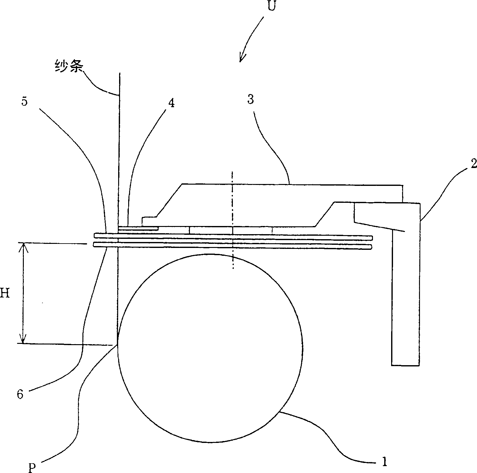
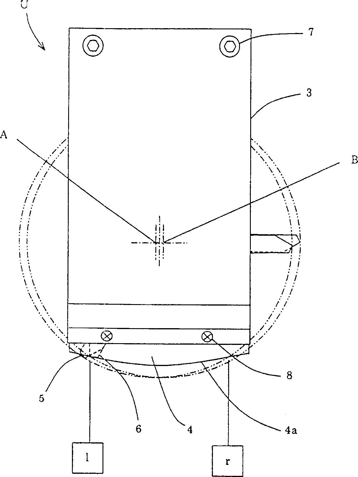
[0036] figure 1 is a front view of the first embodiment of the present invention. figure 2 yes figure 1 side view. image 3 express figure 1 floor plan.

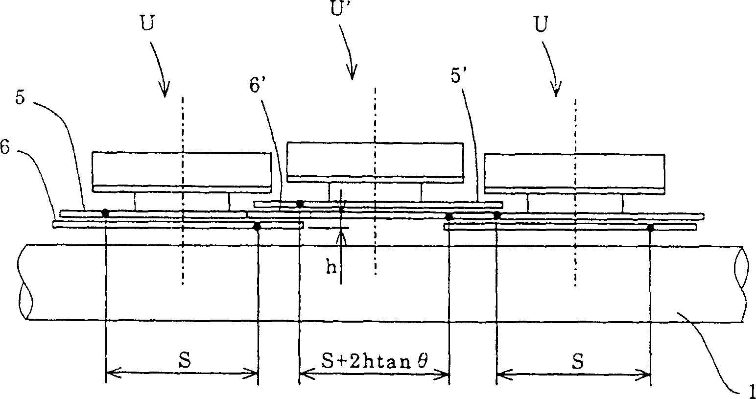
[0037] The contact roller 1 is rotatably supported on the frame 2 by known means not shown in the figures, upstream of the contact roller 1 with respect to the travel path of the sliver, the traversing means U, U' for reciprocating the sliver Alternating horizontal configurations.

[0038] In addition, in this application document, "for each bobbin ... has contact rollers", it is not limited to having a plurality of contact rollers corresponding to each bobbin, but also includes, as in this embodiment, for the traversing devices U, U' adopting The case of a shared touch roll 1.

[0039] In the traversing device U, the configuration in the housing 3 can be ce...


PUM


Abstract

Provide is a yarn winding device capable of providing a package with a uniform winding width even when a distance between a rotary vane and a point where the yarn contacts a contact roller, that is a free length, is different when the yarn is released from the rotary vane between adjoining vane traverse devices. This yarn winding device comprises the traverse devices for traversing the yarn along a guide rail by an upper and lower pair of the rotary vanes rotating in the opposite directions for at least two respective adjoining bobbins for winding the yarn and the contact roller arranged in upstream of the bobbins for a yarn traveling yarn guide and has different free length between the adjoining traverse devices. By making different rotational radii formed by tips of the rotary vanes between the traverse devices, the winding width of each package wound between the traverse devices is uniformized.

Description

technical field [0001] The invention relates to a sliver take-up device using a so-called blade traversing device. Background technique [0002] Conventionally, as an inexpensive sliver winding device that can be easily attached and detached from each traverse device, for example, a device described in JP-A-5-24740 is known. The device described in JP-P-5-24740 communiqué, such as Figure 11 As shown, the arrangement is such that the rotation plane m of the upper rotating blade 5 of one of the adjacent blade traversing devices U and U' and the rotation plane m of the lower rotating blade 6 of the other traversing device U' The plane of rotation n is on the same plane X. Moreover, the rotating blades 5 and 6 on the same plane rotate in opposite directions, and their structure is like gear meshing. [0003] However, such existing traverse devices, such as Figure 11 As shown, the free length, i.e. the distance from the rotating blade when the sliver is released from the rota...

Claims


Application Information

Patent Timeline
Patent Type & Authority Applications(China)
IPC IPC(8): B65H54/28B65H45/22
Inventor 杉冈隆美中村节夫浅川勇一郎
Owner TSTM CO LTD
Why Eureka
Try Eureka