
Automobile frame

A technology of automobile frame and frame, which is applied in the direction of vehicle components, substructure, transportation and packaging, etc. It can solve the problems of occupying a lot of space, increasing the self-weight of the longitudinal beam, and the difficulty of increasing the rigidity and bearing capacity of the longitudinal beam of the frame. Reduce the weight of the structure, increase the rigidity of the frame longitudinal beam, and improve the effect of rigidity

Inactive Publication Date: 2008-03-12
廖松山
View PDF4 Cites 0 Cited by
  • Summary
  • Abstract
  • Description
  • Claims
  • Application Information

AI Technical Summary

Problems solved by technology

[0002] Most automobiles use the frame of the chassis as the matrix for the support and connection of various parts. Under the conditions of use of the commonly used frame longitudinal beams, the longitudinal beams, the main components of the frame, will deform under the action of their own weight and load and show a downward deflection trend. The downward deflection and bending deformation of the longitudinal beam of the frame with a long wheelbase is particularly obvious after being loaded; the solution in the prior art is to increase the flexural modulus of the longitudinal beam section to improve its rigidity, such as increasing the flexural cross-sectional area or size , and the method of increasing the flexural section modulus of the longitudinal beam will increase the self-weight of the longitudinal beam or occupy more space
Therefore, in the case of limited weight and space, it is not easy to increase the rigidity of the frame rails of this type of structure to enhance the load-bearing capacity of the frame

Method used


Image

  • Automobile frame
  • Automobile frame
  • Automobile frame

Examples


Embodiment Construction

[0025] The present invention will be further described below in conjunction with the accompanying drawings and embodiments.

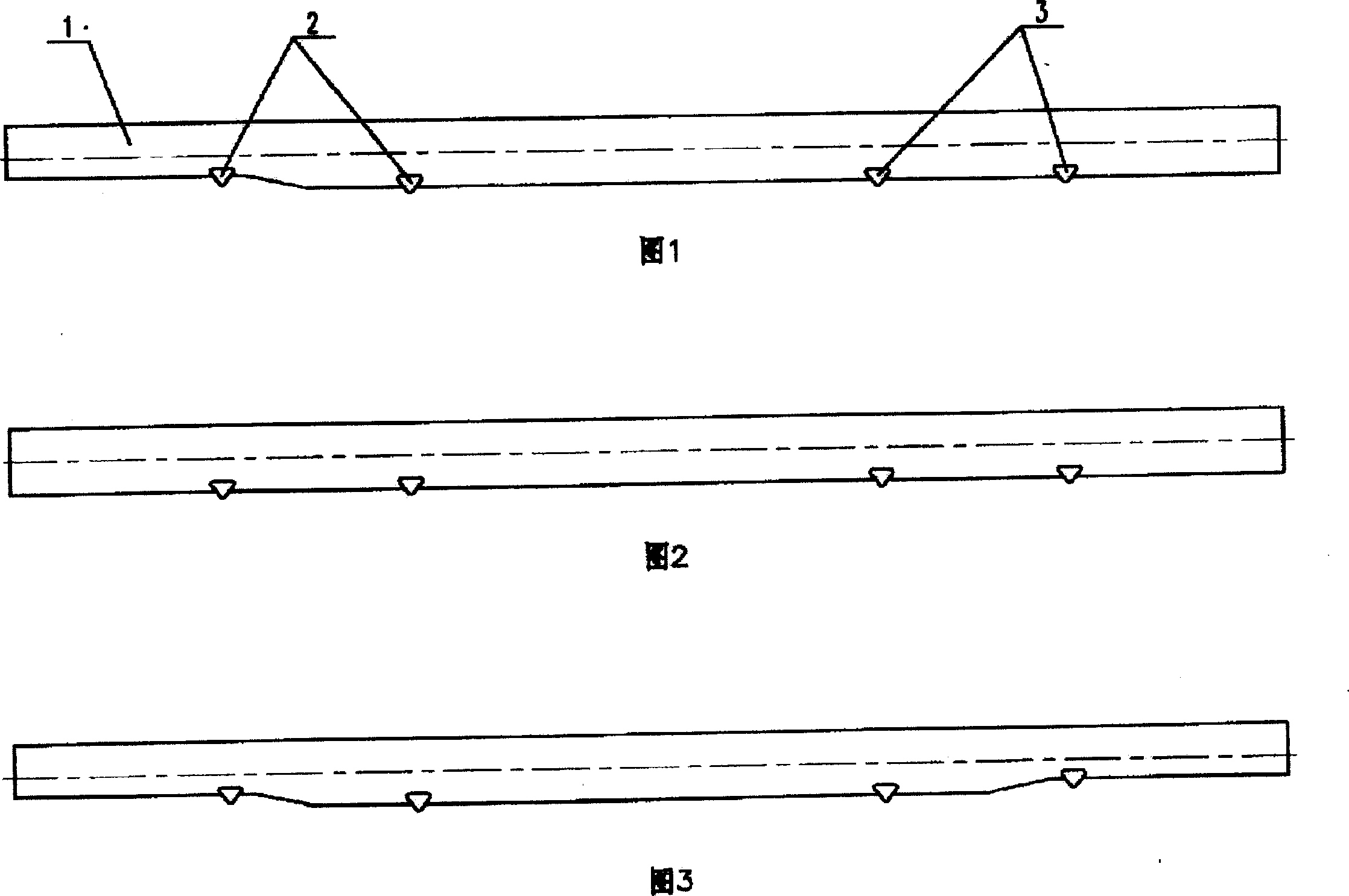
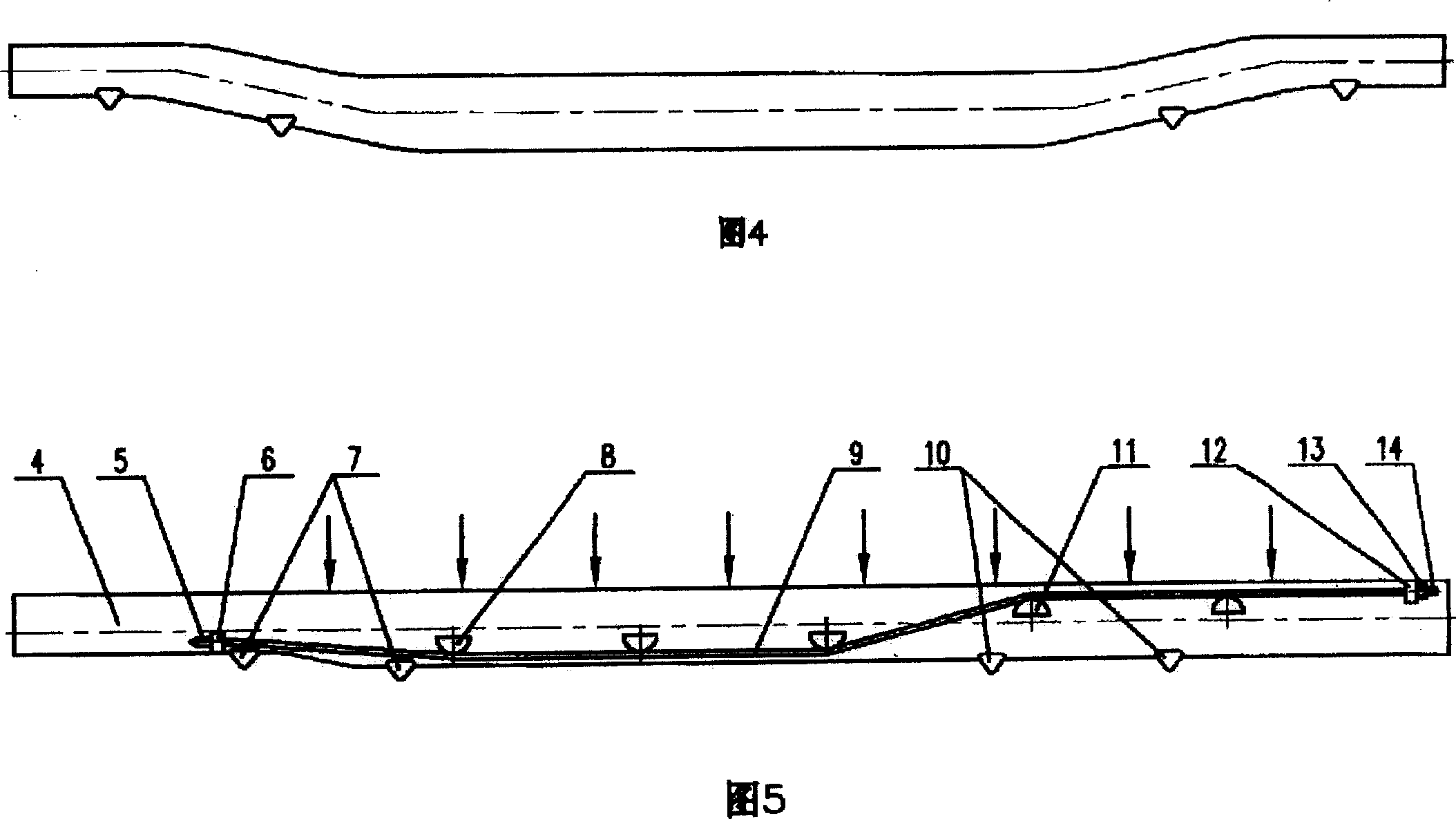
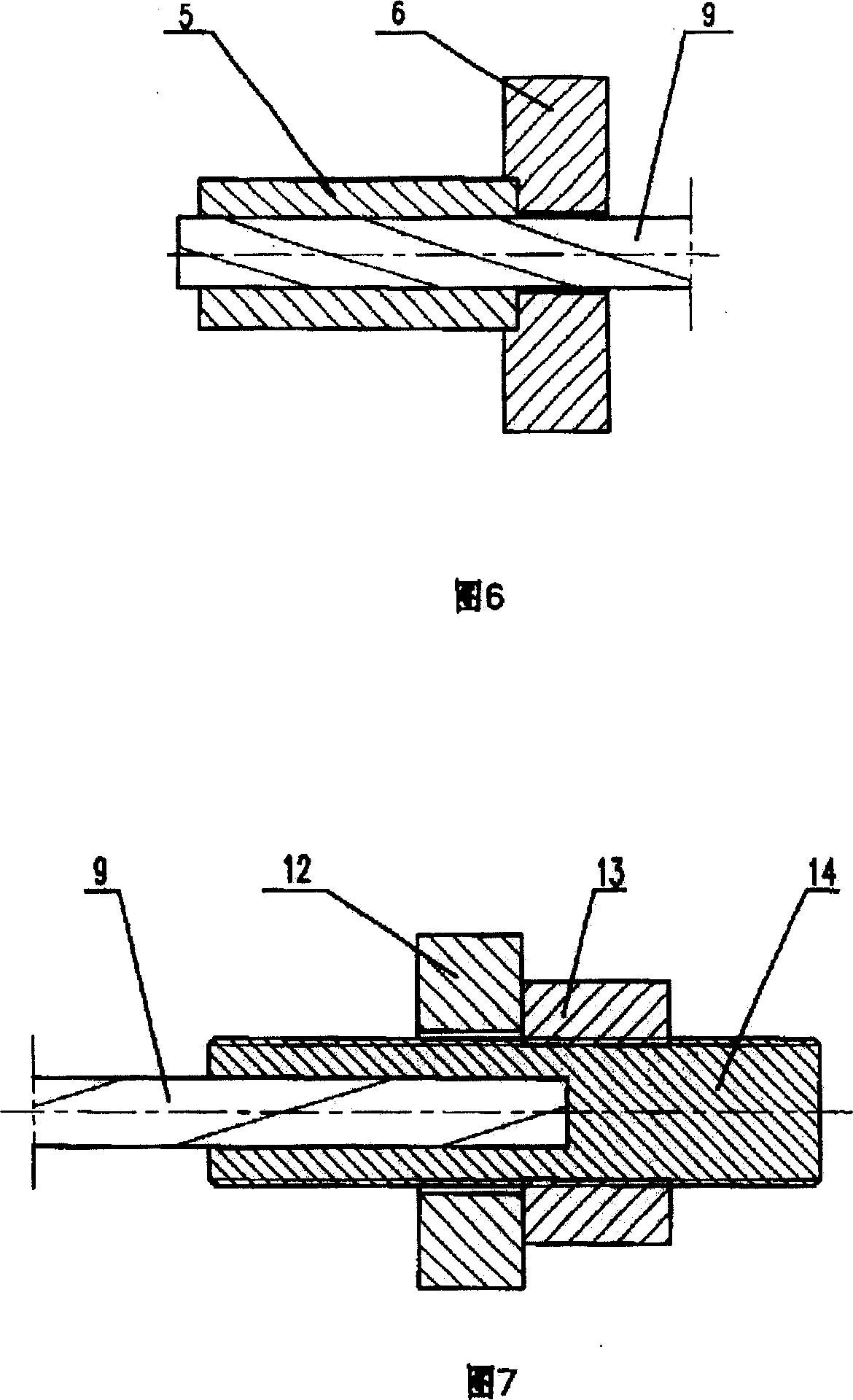
[0026] Shown in Fig. 1, in the automobile frame of prior art, front wheel support 2 and rear wheel support 3 are housed on longitudinal beam 1, the vehicle frame of this structure is under the condition of use, and the longitudinal beam 1 of vehicle frame is under self-weight And under the action of load, it will show downward deflection. The upper part of the longitudinal beam 1 before the front wheel support 2, the lower part of the longitudinal beam 1 between the front wheel support 2 and the rear wheel support 3, and the upper part of the longitudinal beam 1 behind the rear wheel support 3 bear tensile stress. The longitudinal beam structures of other vehicle frames in the prior art are not much different from this, as shown in Fig. 2, Fig. 3, and Fig. 4, only the variation of the section size and the undulation of the horizontal direction are arran...


PUM


Abstract

Disclosed a vehicle frame relates to the chassis technique of vehicle, comprising a frame longitudinal beam which is connected to an attaching means for preventing the partly stretching distortion of said longitudinal beam while its tensile strength is more than the tensile strength of the material of longitudinal beam. Compared to present technique, the invention can attain more rigidity of longitudinal beam.

Description

Technical field [0001] The invention relates to the technical field of automobile chassis, in particular to the vehicle frame of the automobile chassis. Background technique [0002] Most automobiles use the frame of the chassis as the matrix for the support and connection of various parts. Under the conditions of use of the commonly used frame longitudinal beams, the longitudinal beams, the main components of the frame, will deform under the action of their own weight and load and show a downward deflection trend. The downward deflection and bending deformation of the longitudinal beam of the frame with a long wheelbase is particularly obvious after being loaded; the solution in the prior art is to increase the flexural modulus of the longitudinal beam section to improve its rigidity, such as increasing the flexural cross-sectional area or size , and the method of increasing the modulus of the flexural section of the stringer will increase the weight of the stringer or take...

Claims


Application Information

Patent Timeline
Patent Type & Authority Patents(China)
IPC IPC(8): B62D21/00
Inventor 廖松山
Owner 廖松山
Learn More