Sloping wedge clamp of building moulding board and mounting, unloading tool thereof

A technology for building templates and dismantling tools, which is applied to the preparation of building components on site, construction, connection parts of formwork/formwork/work frame, etc., and can solve complex structures, difficult users, and no P-direction adjustment force, etc. question

Inactive Publication Date: 2008-03-12
潘颖聪
View PDF7 Cites 0 Cited by
  • Summary
  • Abstract
  • Description
  • Claims
  • Application Information

AI Technical Summary

Problems solved by technology

In addition, the conditions of each construction site are different, and the screws require different lengths, so there are few chances of repeated use.
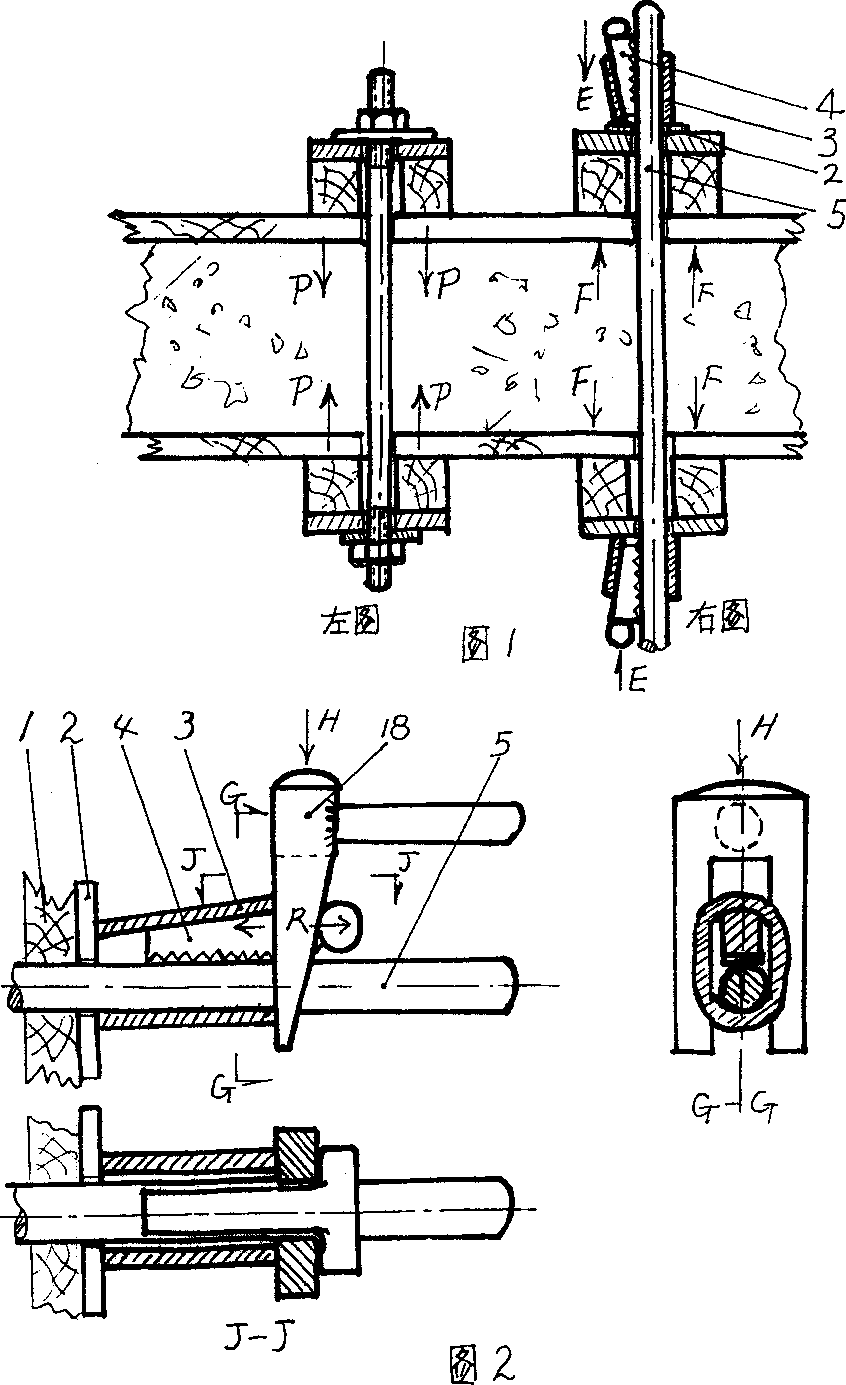
[0003] The patent closest to the present invention is the patent No. 94213579.2 "Formwork Tie Rod Clamp". In this patent technology, the tie rod and wedge are assembled and disassembled and can be reused. The performance is undoubtedly a big step forward compared with the screw rod, but the biggest disadvantage It does not produce the P-direction adjustment force shown in the left picture of Figure 1. In addition, the structure is also complicated and the cost is high, because each construction site does not use a thousand or several hundred sets, but a few thousand sets at a minimum, and more than ten sets Ten thousand sets is a large equipment investment. In fact, the important disadvantage of this patented technology is that the equipment cost is increased by connecting the loading and unloading tools to the fixture, so it is difficult for users to accept.

Method used


Image

  • Sloping wedge clamp of building moulding board and mounting, unloading tool thereof
  • Sloping wedge clamp of building moulding board and mounting, unloading tool thereof

Examples


Embodiment Construction

[0018] Below according to the accompanying drawings 1, 2, 3, the specific implementation method of the present invention is exemplified for further details.

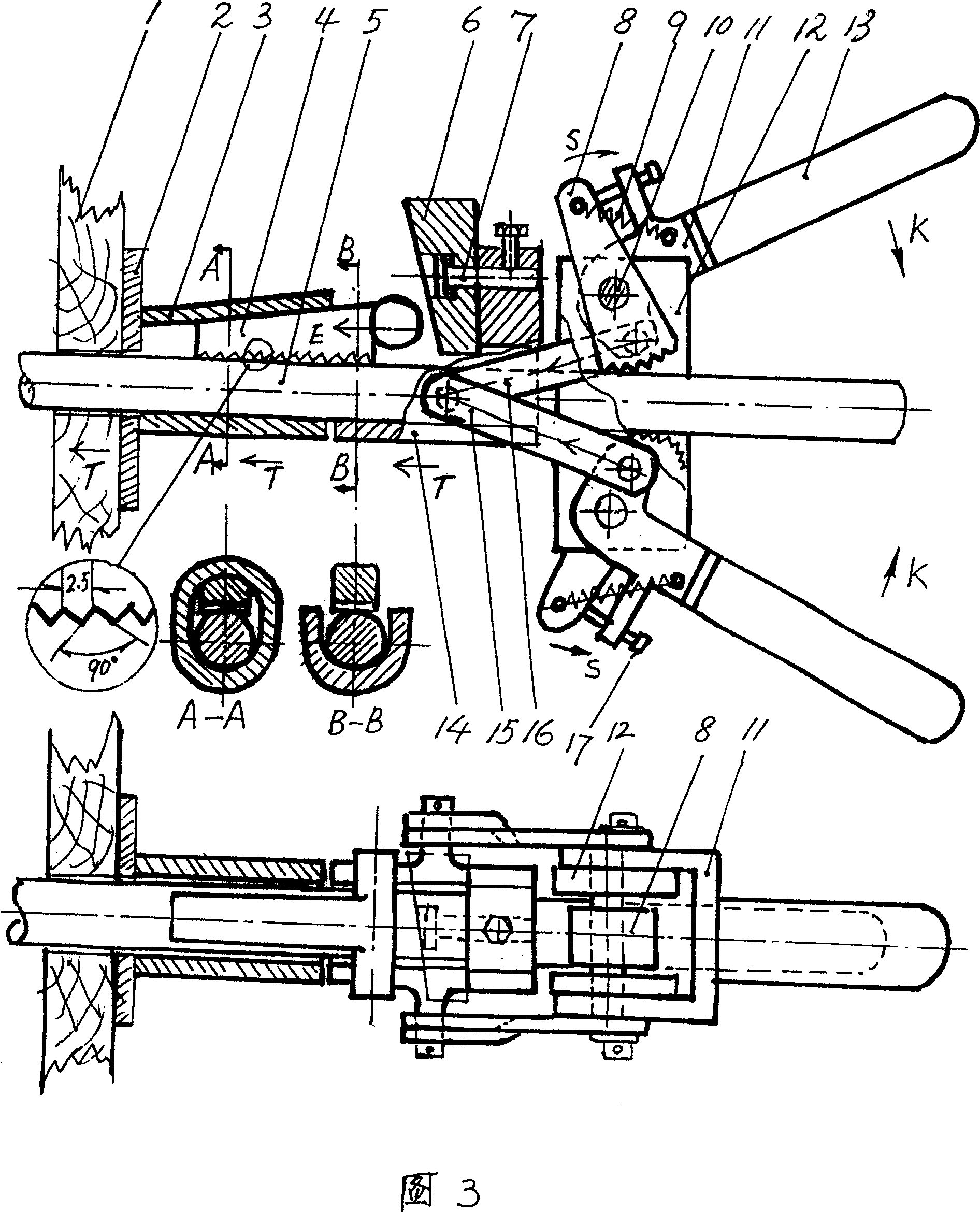
[0019] According to Figure 1, the picture on the right is the general construction formwork clamping method. First put on the polished rod 5, install the inclined sleeve 3 and the inclined wedge 4 on both ends, and first use a hammer to knock the inclined wedge 4 on one end into the inclined sleeve according to the E direction. 3, and the other end is inserted into the installation tool pliers as shown in Figure 3. When the two handles 13 are forced in the K direction, the stop ratchet 8 bites into the polished rod 5 and withstands the clamp body 12 without sliding back. 3. Push forward, because the other end of the polished rod 5 has been clamped into a set of fixtures to withstand the other side of the formwork, so it cannot be retreated. The inclined sleeve 3 can only be advanced in the direction of T, and the inclined...


PUM


Abstract

The inclined wedged fixture and assembling and disassembling tool for building formwork includes polished rod, inclined wedge and characterized inclined sleeve being one long flat steel pipe with hole in the same axial inclination as that of the inclined wedge. The polished rod is penetrated into the hole of the inclined sleeve, and the inclined wedge is wedged into the interval between the polished rod and the inclined sleeve hole. The present invention has separated fixture and assembling and disassembling tool, the formwork position may be regulated with installing pliers with crank link mechanism, and the fixture may be detached with the inclined wedge. The technology of the present invention is simple and reliable, and has easy assembling and disassembling and low cost.

Description

technical field [0001] The utility model relates to a fixture and a loading and unloading tool for fast loading and unloading of building templates. Background technique [0002] Nowadays, powerful vibrators are used to tamp the concrete on the construction site. Due to the large vibration force, the requirements for the firmness and stability of the formwork are also high. The easiest and most effective method is of course to clamp with a screw rod, as shown in the attached picture Like the left picture of Figure 1, it is a typical example of a rammed concrete wall. The screw rod passes through the two formworks, and the two formworks are kept to the thickness of the concrete wall to be rammed and pressed tightly. When the concrete is rammed, the screw maintains the thickness of the formwork position and withstand the expansion force of the concrete and the vibration force of the vibrator. The screw also has a function to generate a P-direction force by twisting the nut whe...

Claims


Application Information

Patent Timeline
Patent Type & Authority Patents(China)
IPC IPC(8): E04G17/07E04G19/00
Inventor 潘颖聪
Owner 潘颖聪
Why Eureka
Try Eureka