Slit nozzle and treating liquid supplying device with such nozzle

A slit nozzle and supply device technology, which is applied to spray devices, spray devices, and devices for coating liquids on surfaces, etc., can solve the problems of high price, long time and labor, and capillary infiltration, etc., to shorten the supply time and shorten the effect of time

Inactive Publication Date: 2008-03-26
TOKYO OHKA KOGYO CO LTD
View PDF9 Cites 0 Cited by
  • Summary
  • Abstract
  • Description
  • Claims
  • Application Information

AI Technical Summary

Problems solved by technology

This processing takes considerable time and labor and is expensive
[0014] In addition, even if the processing accuracy is improved endlessly, because the width of the slit nozzle is widened, only a part of a very small gap is formed on the merged surface, and the capillary phenomenon penetrates into the treatment liquid due to the gap.

Method used


Image

  • Slit nozzle and treating liquid supplying device with such nozzle
  • Slit nozzle and treating liquid supplying device with such nozzle
  • Slit nozzle and treating liquid supplying device with such nozzle

Examples


Embodiment Construction

[0029] [Invention embodiment]

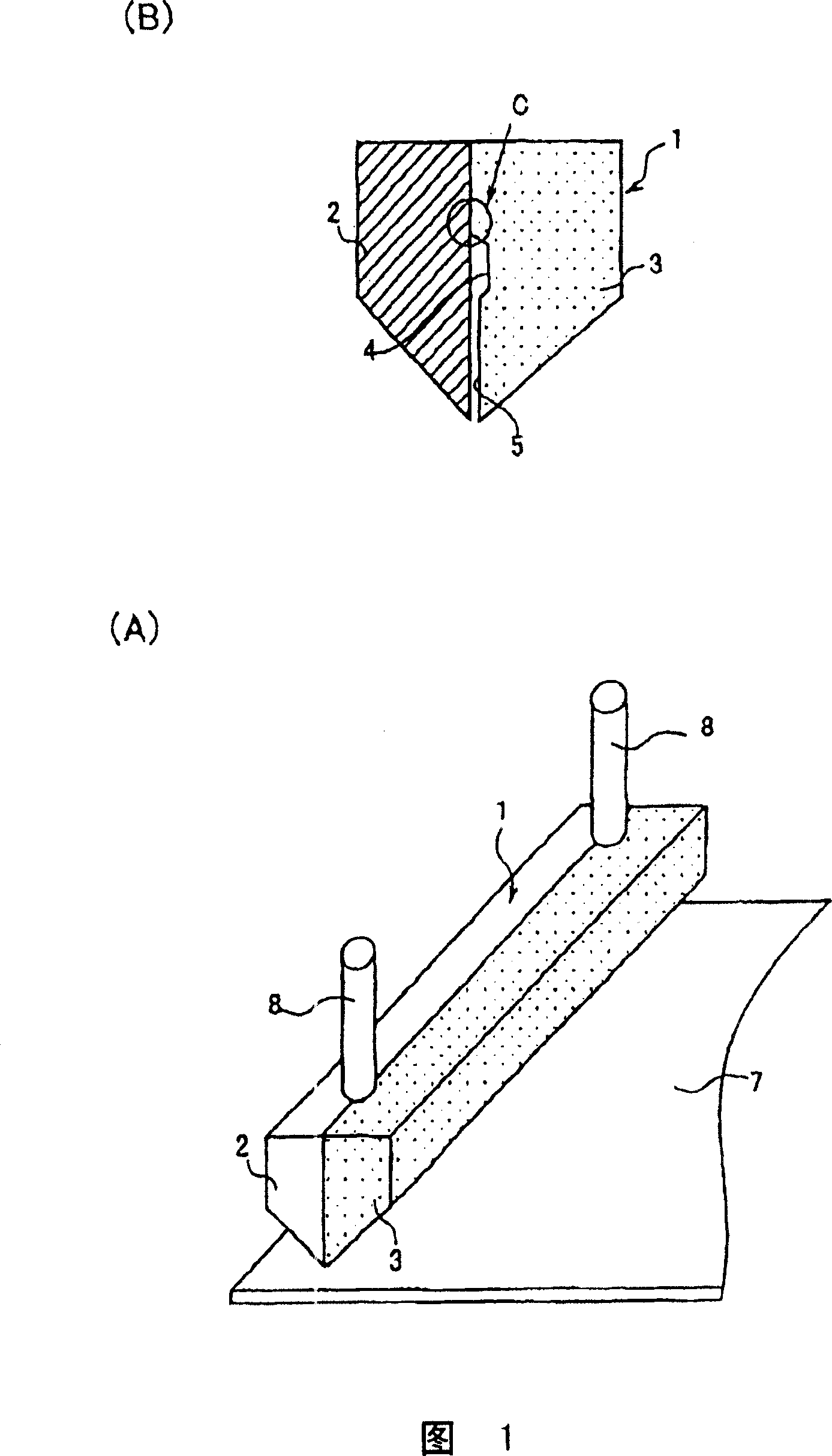
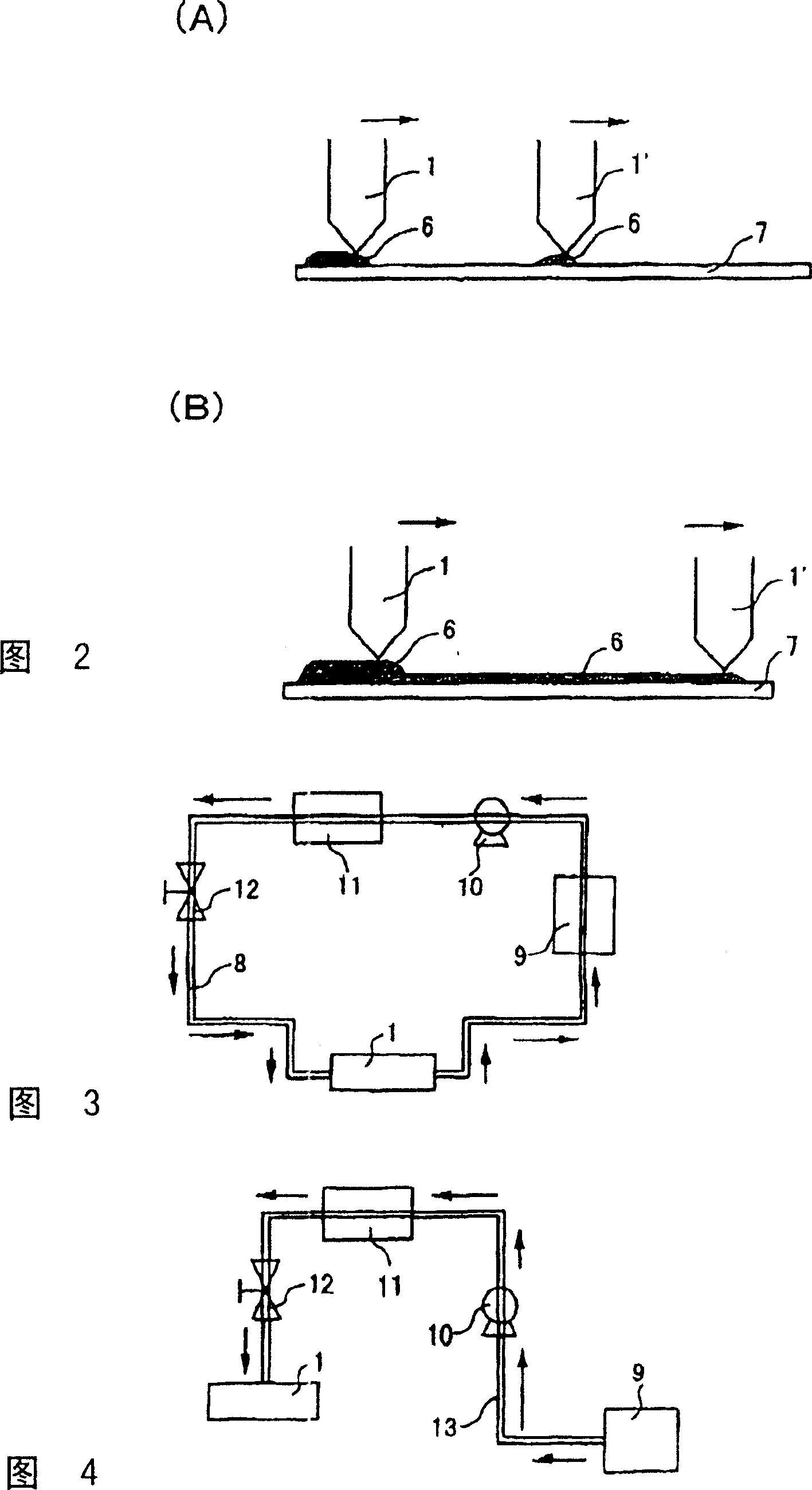
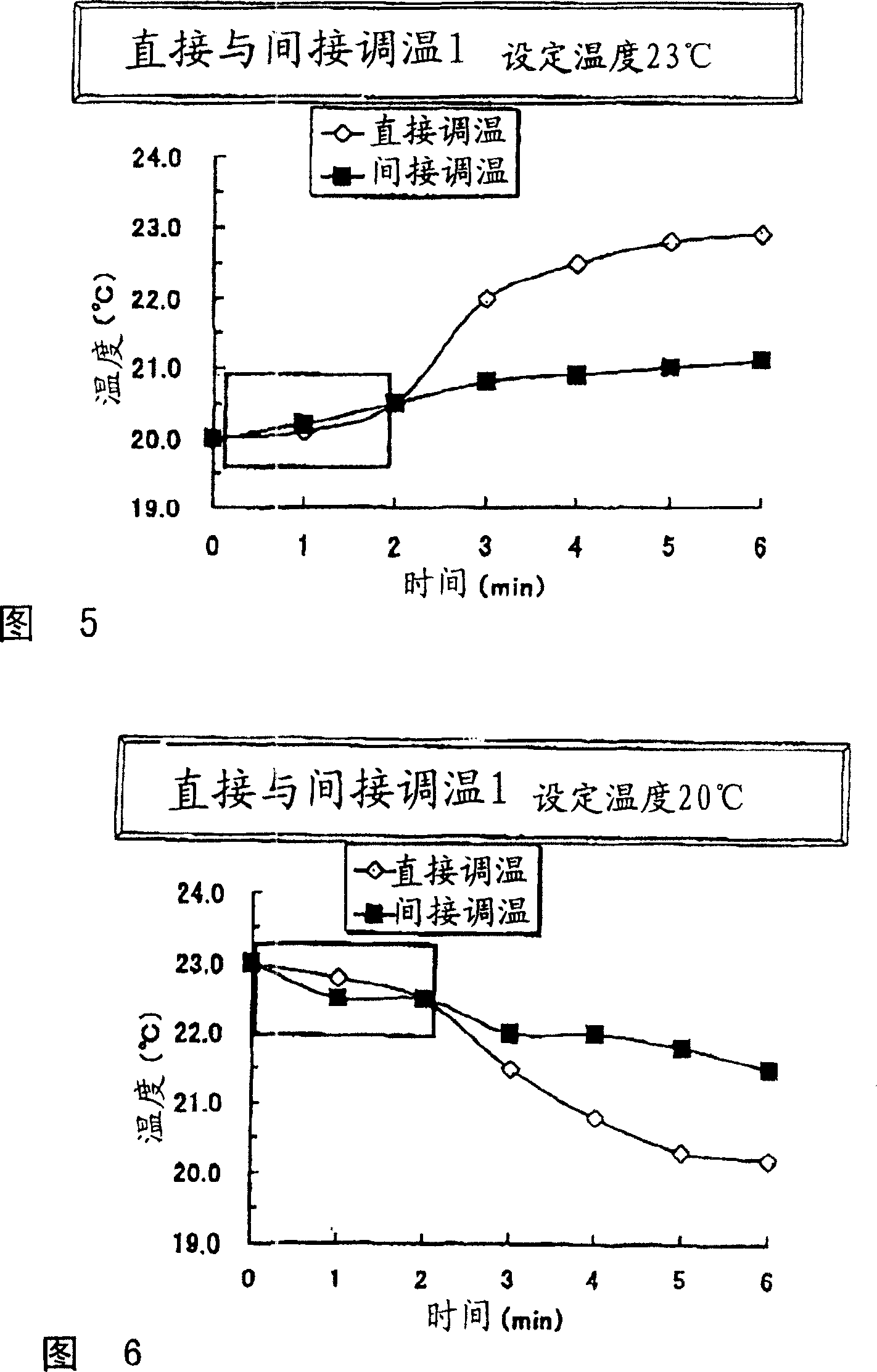
[0030] Embodiments of the present invention will be described below with reference to the drawings. Here, Fig. 1 (A), (B) is a side view and an enlarged sectional view of a slit nozzle of the present invention, and Fig. 2 (A), (B) is a process of supplying a treatment liquid using a plurality of slit nozzles of the present invention. Schematic diagram, Fig. 3 is a schematic diagram of direct temperature regulation with a slit nozzle and a temperature regulator of the present invention. Fig. 4 is a schematic diagram of indirect temperature regulation of a conventional device.

[0031] As shown in Figure 1, the slit nozzle 1 is composed of a left half body 2 made of titanium and a right half body 3 made of PPS (polyphenylene sulfide). channel) and a flat surface 5 forming a longitudinal flow path shallower than the bottom surface of the recess 4. Furthermore, the left half body 2 may also be made of stainless steel.

[0032] In this way, by ma...


PUM


Abstract

A slit nozzle and a treating solution supplying device using the slit nozzle are provided, to allow a slit nozzle to be processed simply and to obtain a slit nozzle free from a capillary phenomenon. The slit nozzle(1) for supplying a treating solution to the surface of a matter to be treated with a certain width, comprises left and right hemi-bodies(2, 3) whose one body(2) is made of a hard material (metallic material) and whose the other body(3) is made of a soft material (resin material). The treating solution supplying device comprises the slit nozzle on the circulation path(8) of a temperature-controlled treating solution. Preferably the treating solution supplying device comprises a plurality of slit nozzles.

Description

[technical field] [0001] The present invention relates to a slit nozzle with different materials on the left and right halves and a processing liquid supply device using the slit nozzle. [Background technique] [0002] Conventionally, there are known slit nozzles in which a nozzle itself opens a coating liquid discharge port with a set width, and the coating liquid is coated with a set width on the surface of the object by moving the nozzle relatively to the object to be processed. Using a slit nozzle having a coating liquid discharge port with such a set width enables efficient coating without wasting the coating liquid. [0003] However, as the size of the object to be processed increases, the supply time and supply amount of one slit nozzle are limited. For example, when the time taken from the start of the supply of the treatment liquid to the end of the supply is too long, treatment unevenness occurs. This also causes the same phenomenon when the treatment liquid is s...

Claims


Application Information

Patent Timeline
Patent Type & Authority Patents(China)
IPC IPC(8): B05B1/34B05C11/10B05C5/02
CPCE02B3/06E02B3/129E02B2201/00
Inventor 岛井太河田茂
Owner TOKYO OHKA KOGYO CO LTD
Why Eureka
Try Eureka