Rotating magnetic field type driver for active controlling torsional vibration of rotational axis system

A rotating magnetic field, active control technology, applied in the direction of suppressing motor vibration control, mechanical vibration control, non-electric variable control, etc., can solve the problems of complex structure and difficult implementation.

Inactive Publication Date: 2008-03-26
TIANJIN UNIV
View PDF4 Cites 0 Cited by
  • Summary
  • Abstract
  • Description
  • Claims
  • Application Information

AI Technical Summary

Problems solved by technology

Some schemes have been proposed for the active control and damping method of torsional vibration of the rotating shaft system, but most of them have complex structures and are difficult to implement

Method used


Image

  • Rotating magnetic field type driver for active controlling torsional vibration of rotational axis system
  • Rotating magnetic field type driver for active controlling torsional vibration of rotational axis system

Examples


Embodiment Construction

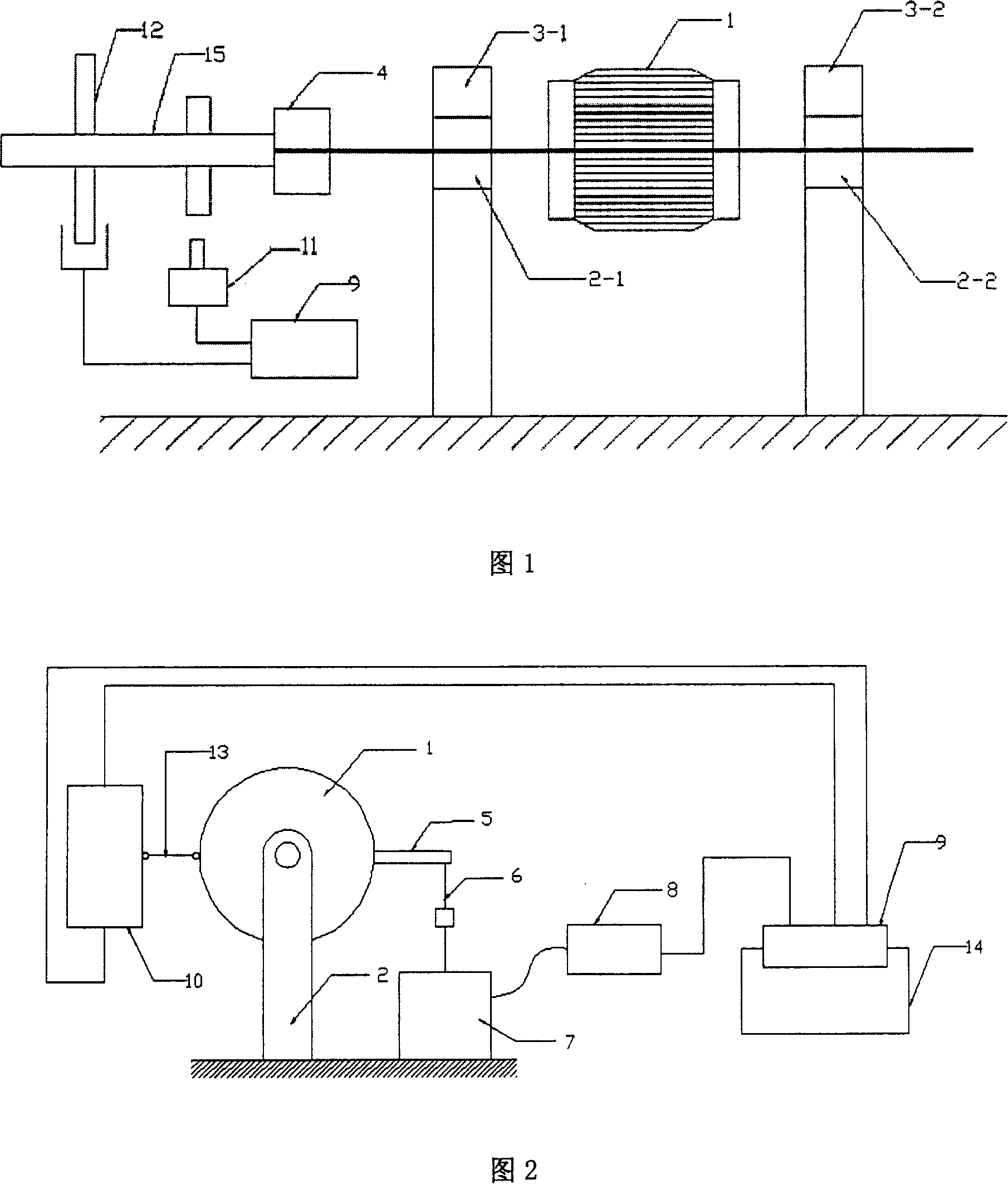
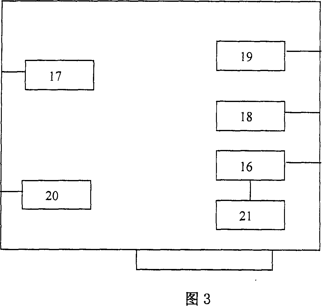
[0009] The structure of the present invention will be further described below through specific embodiments and in conjunction with FIG. 1 and FIG. 2 . Motor 1 adopts a three-phase squirrel-cage motor with extended shaft, bearing 2-1 and bearing 2-2 are ball bearings, two supports 3-1, 3-2, coupling 4, stator rotating rod 5, and connecting rod 6 For general machining parts. The linear vibrator 7, the power amplifier 8, and the frequency converter 10 are all general products. Computer 14 adopts industrial control computer, and computer interface board 9 internal circuit block diagrams are as shown in Figure 3, and the circuit chip that computer interface board 9 adopts is as follows: speed counter 19 selects Intel 8254 for use; Filter amplifier 16 selects op07 for use; Exciting signal D / A converter 17 and motor speed regulating D / A converter 20 use dac1210; speed A / D converter 18 and torsional vibration A / D converter 21 use ad574. The computer interface board 9 is installed in...


PUM


Abstract

The driver includes motor, dwang of stator, and link rod, and straight vibrator, interface board of computer, frequency converter and revolution speed sensor. Measuring apparatus for torsional vibration and revolution speed sensor are installed on working-spindle series. Output signals of measuring apparatus for torsional vibration and revolution speed sensor are connected to interface board of computer. Output end of D / A converter of vibration signal in interface board of computer is connected to the input end of power amplifier. D / A converter for speed regulation of motor controls frequency converter to output frequency of power source. Through dwang of stator and link rod, the motor is connected to straight vibrator to make stator of motor generate superimposed components of rotating magnetic field and torsional vibration.

Description

technical field [0001] The invention belongs to the control technology of shafting torsional vibration in electric and mechanical systems. Background technique [0002] In aviation, spaceflight, electric power, machinery, engine and other industries, the torsional vibration of shafting is a problem worthy of attention. Shafting torsional vibration is easy to damage the shafting unknowingly, resulting in significant economic losses. Due to the complexity of some shafting structures, approximate assumptions or empirical formulas are mostly used in the current calculation and analysis of torsional vibration, so that the results of the current theoretical analysis of shafting torsional vibration, especially the torsional vibration amplitude and The torsional vibration stress value deviates greatly from the actual value, so after the theoretical calculation and analysis of the torsional vibration characteristics of the shafting system, it is necessary to carry out the torsional ...

Claims


Application Information

Patent Timeline
Patent Type & Authority Patents(China)
IPC IPC(8): H02P23/04H02P27/06F16F15/00G05D19/02
Inventor 张俊红刘杰倪广健
Owner TIANJIN UNIV
Why Eureka
Try Eureka