Cooling device and refrigerator using the same

A technology for cooling devices and refrigerators, which is applied to cooling fluid circulation devices, household refrigerators, household refrigeration devices, etc., can solve problems such as difficulty in refrigerant flow and sound.

Inactive Publication Date: 2008-04-23
PANASONIC CORP
View PDF7 Cites 0 Cited by
  • Summary
  • Abstract
  • Description
  • Claims
  • Application Information

AI Technical Summary

Problems solved by technology

[0005] However, when the above-mentioned existing structure is used in a direct-cooling refrigerator or a refrigerator with a large amount of sealed refrigerant, it is difficult to reduce the sound of refrigerant flow due to the increase in the amount of sealed refrigerant.

Method used


Image

  • Cooling device and refrigerator using the same
  • Cooling device and refrigerator using the same
  • Cooling device and refrigerator using the same

Examples


Embodiment Construction

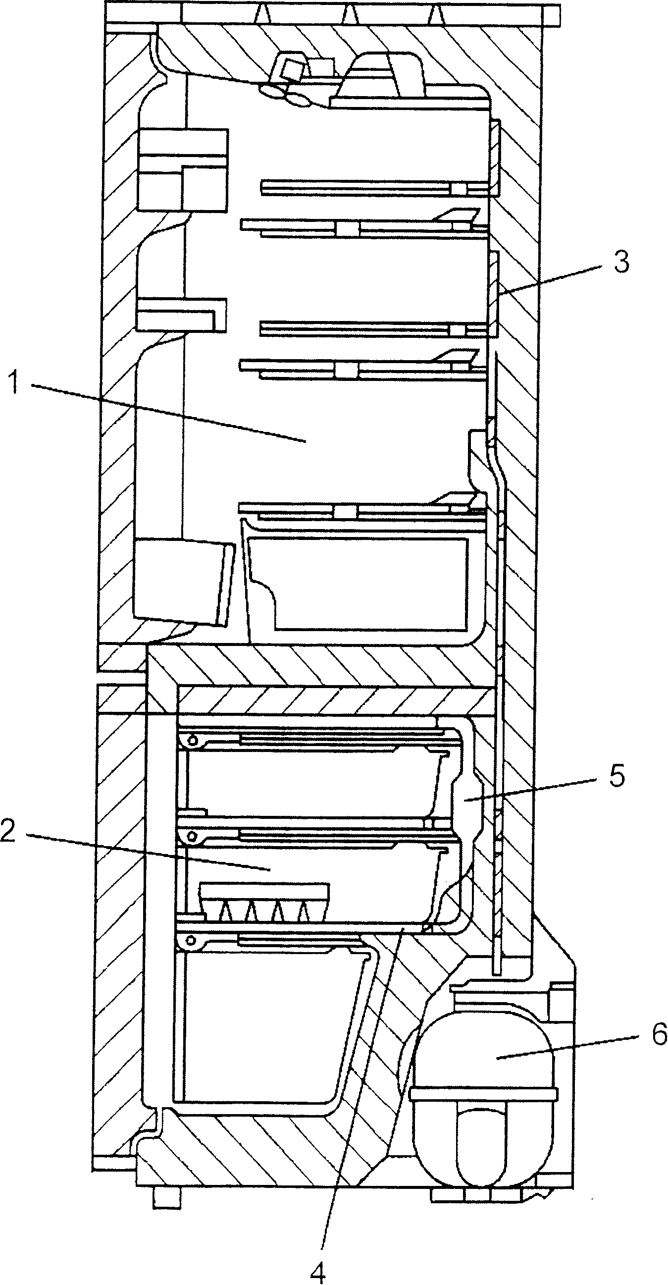
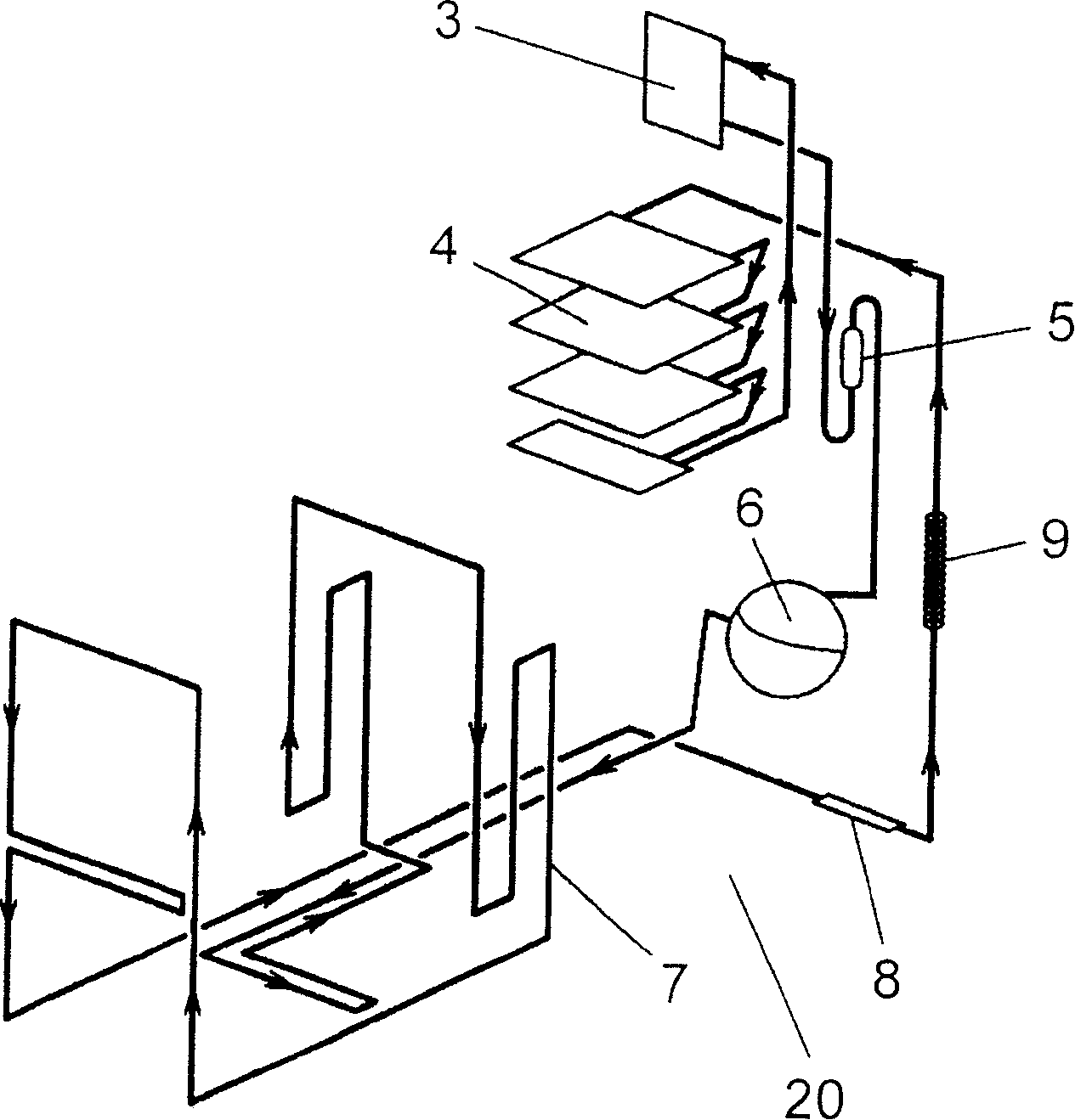
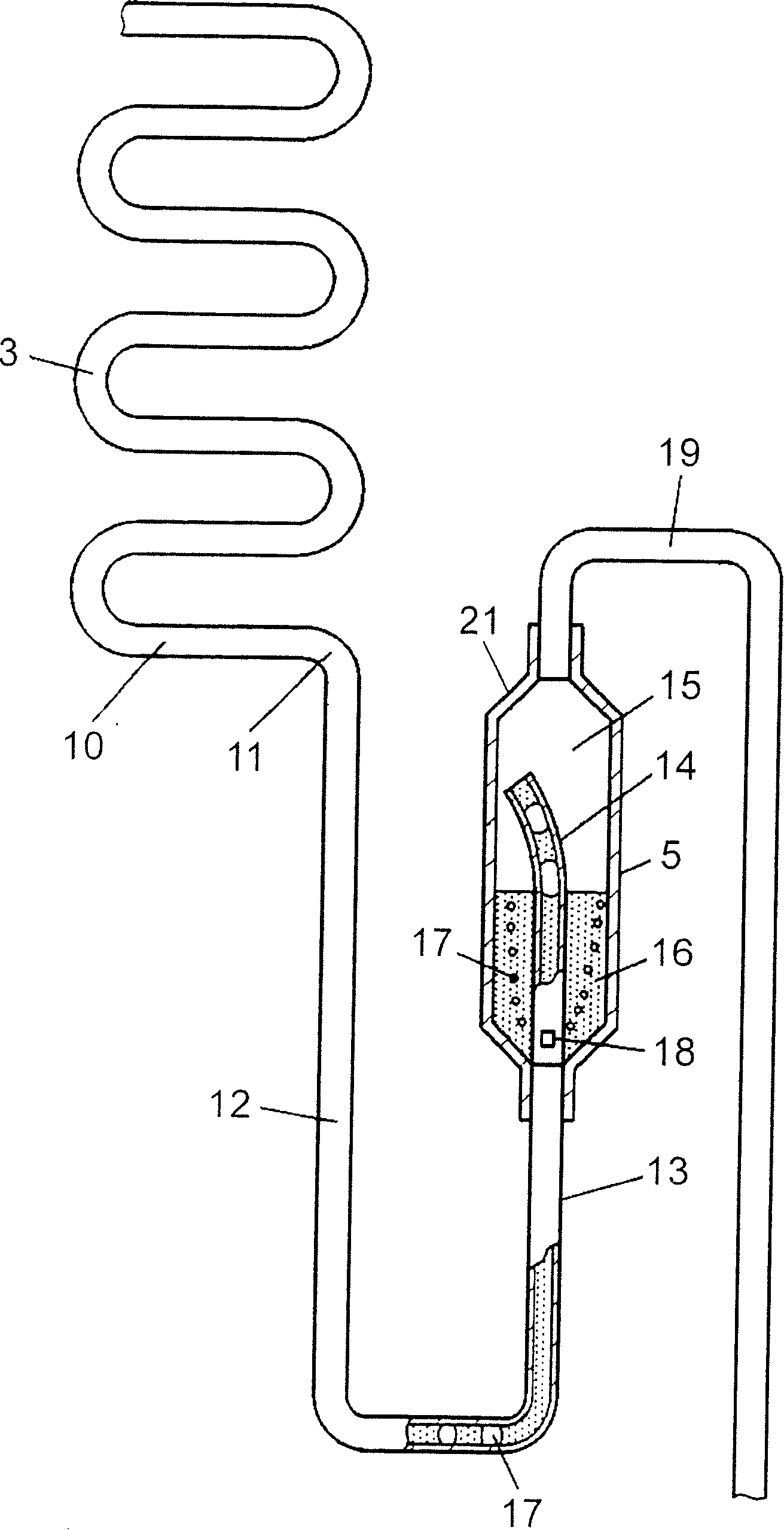
[0016] figure 1 It is a schematic cross-sectional view of a refrigerator according to an embodiment of the present invention. figure 2 It is a refrigeration cycle diagram of the cooling device incorporated in the refrigerator, image 3 It is an enlarged view of the main part of the accumulator of the cooling device and the evaporator for the refrigerator compartment.

[0017] In the refrigerator of this embodiment, the refrigerator compartment 1 and the freezer compartment 2 are divided up and down. The refrigerator compartment 1 is provided with a first evaporator, namely, a refrigerator compartment evaporator (hereinafter referred to as an evaporator) 3, and a second evaporator, namely, a refrigerator compartment evaporator (hereinafter referred to as an evaporator) 4 is installed in the freezing compartment 2. A reservoir 5 is provided on the back of the freezer compartment 2. In addition, such as figure 2 As shown, the cooling device 20 of the refrigerator in this embodime...


PUM


Abstract

A cooling device, wherein a compressor, a condenser, a capillary, an evaporator, and an accumulator are connected to each other in this order and a refrigerant is circulated therethrough. A U-trap tube is installed between the evaporator and the accumulator.

Description

Technical field [0001] The present invention relates to a cooling device that reduces the sound of refrigerant flowing in a cooling pipe in a refrigeration cycle, and a refrigerator using the cooling device. Background technique [0002] Figure 6 It is a freezing cycle diagram of an existing refrigerator. The refrigeration cycle is composed of a compressor 36, a condenser 37, a dryer 38, a capillary tube 39, an evaporator for the refrigerator compartment (hereinafter referred to as an evaporator) 33, an evaporator for a freezer compartment (hereinafter referred to as an evaporator) 34, and an accumulator 35 And the piping connecting them. [0003] Figure 7 Is showing Figure 6 An enlarged view of the accumulator 35 and the evaporator 34 in. The refrigerant in the tube of the evaporator 34 during the cooling operation forms a gas-liquid two-phase flow of the gas refrigerant 45 generated by evaporation and the liquid refrigerant 46 that is not evaporated. The liquid refrigerant...

Claims


Application Information

Patent Timeline
Patent Type & Authority Patents(China)
IPC IPC(8): F25B43/00F25D19/00F25B11/02F25B5/04F25B41/00F25D11/02
CPCF25D11/022F25B43/006F25B41/003F25D2400/04F25B41/40
Inventor 多田嘉孝
Owner PANASONIC CORP
Why Eureka
Try Eureka