
Electric valve

A technology of electric valve and valve port, applied in the direction of lift valve, valve details, valve device, etc., can solve the problems of high differential pressure of valve port, high noise, non-deceleration of flow rate, etc., and achieve the effect of reducing flow rate sound, noise and deceleration. high effect

Active Publication Date: 2019-09-06
SAGINOMIYA SEISAKUSHO INC
View PDF1 Cites 0 Cited by
  • Summary
  • Abstract
  • Description
  • Claims
  • Application Information

AI Technical Summary

Problems solved by technology

Therefore, the fluid is rectified, but the flow velocity in the second port does not slow down, and noise may be generated due to flow velocity sound (sound caused by a high flow velocity)
In particular, when the load is high, the differential pressure between the front and back of the valve port is high, and this flow velocity sound becomes an important factor for the high noise.

Method used


Image

  • Electric valve
  • Electric valve
  • Electric valve

Examples


Embodiment Construction

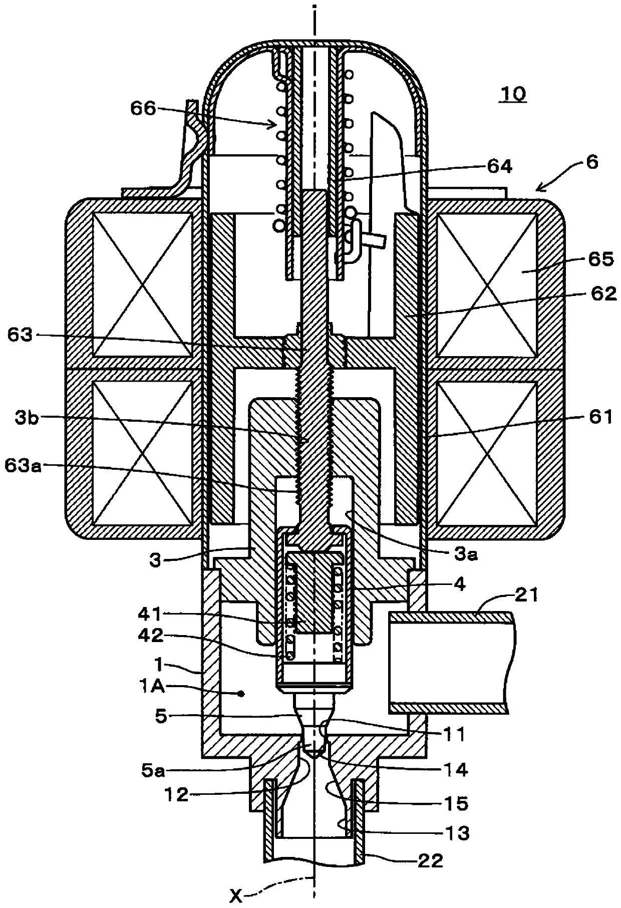
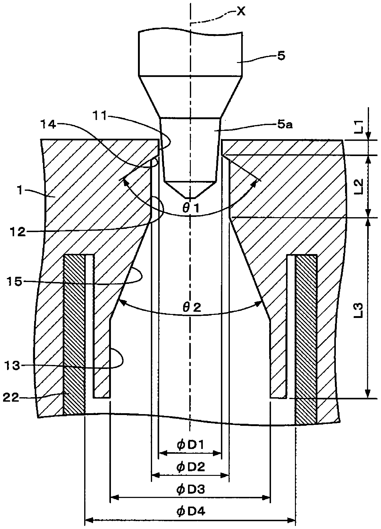
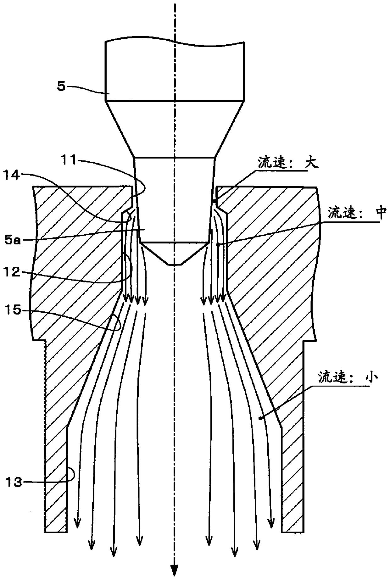
[0033] Next, embodiments of an electric valve according to the present invention will be described with reference to the drawings. figure 1 is a longitudinal sectional view of the electric valve of the embodiment, figure 2 It is an enlarged longitudinal sectional view of main parts near the valve port of the electric valve according to the embodiment, image 3 It is a figure explaining the function of the valve port of the electric valve of embodiment, Figure 4 It is a figure which shows an example of the air conditioner which used the electric valve which concerns on embodiment.

[0034] First, based on Figure 4 The air conditioner of embodiment is demonstrated. The air conditioner has the electric valve 10 of the embodiment, the outdoor heat exchanger 20 mounted on the outdoor unit 100, the indoor heat exchanger 30 mounted on the indoor unit 200, the flow path switching valve 40, and the compressor 50, and these elements are passed through The pipes are connected as ...


PUM


Abstract

The invention provides an electric valve. In the electric valve in which the flow rate of the refrigerant is controlled by opening and closing the valve port of the needle valve, the noise generated by the flow of the refrigerant at the valve port is reduced. A first port (11) with an inner diameter D1, a second port (12) with an inner diameter D2, a third port (13) with an inner diameter D3, a first tapered portion (14) and a circular cross-sectional shape are formed on the valve housing (1). The second tapered portion (15). When the flowing refrigerant flows out of the second port (12) from the gap between the first port (11) and the needle valve (5a), the pressure in the second port (12) does not recover sharply, and the flow is rectified to make The flow is stable. The collapse of the cavities is thereby suppressed. When flowing from the second port (12) to the second tapered portion (15) and the third port (15), the flow speed is decelerated to reduce the flow sound.

Description

technical field [0001] The present invention relates to a needle type electric valve for controlling the flow rate of refrigerant in an air conditioner, and more particularly to an electric valve in which the shape of the valve port relative to the needle valve is improved. Background technique [0002] Conventionally, in the refrigerating cycle, the noise generated from the electric valve controlling the flow rate of the refrigerant and accompanying the passage of the fluid has often been a problem. As an electric valve for implementing such noise countermeasures, there is, for example, an electric valve disclosed in Japanese Patent No. 5696093 (Patent Document 1). [0003] In the electric valve disclosed in Patent Document 1, the valve port is composed of a first port and a second port, and a tapered portion is provided between the first port and the second port. In addition, the inner diameter of the second port is slightly larger than that of the first port, and the len...

Claims


Application Information

Patent Timeline
Patent Type & Authority Patents(China)
IPC IPC(8): F16K47/02F16K1/00F16K27/02
CPCF16K27/0254F16K47/02F16K1/32Y02B30/70
Inventor 小林一也中川大树
Owner SAGINOMIYA SEISAKUSHO INC
Learn More