Spray bore slice

An orifice sheet and orifice technology, applied in printing and other directions, can solve problems such as damage to the anti-wetting layer, scratches, and skew in the direction of droplet ejection.

Inactive Publication Date: 2008-06-04
IND TECH RES INST
View PDF6 Cites 0 Cited by
  • Summary
  • Abstract
  • Description
  • Claims
  • Application Information

AI Technical Summary

Problems solved by technology

However, the inner edge of the injection hole adjacent to the injection hole sheet in the anti-wetting layer is easily scratched by the scraper for cleaning, thereby causing damage to the inner edge of the anti-wetting layer adjacent to the injection hole, which may cause liquid Drop ejection direction is skewed

Method used


Image

  • Spray bore slice
  • Spray bore slice
  • Spray bore slice

Examples


Embodiment Construction

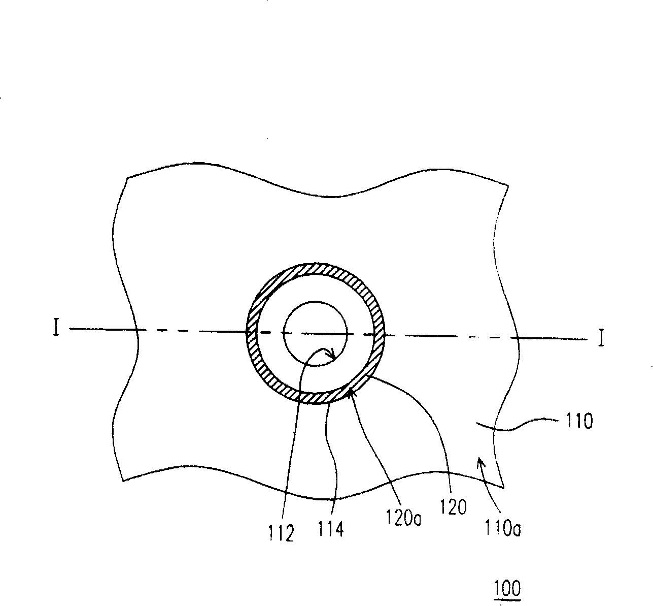
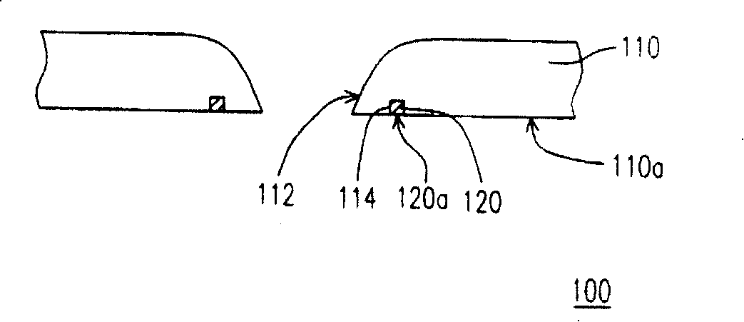
[0073] Figure 1A is a partial top view of an orifice sheet according to the first embodiment of the present invention, Figure 1B for Figure 1A Sectional view of the line I-I. Please refer to Figure 1A and Figure 1B , the orifice sheet 100 of the first embodiment is suitable for an inkjet print head and includes an orifice layer 110 . The orifice layer 110 has an orifice 112 , which runs through the orifice layer 110 , so that the inkjet printing head using the orifice sheet 100 can eject ink droplets or liquid droplets through the orifice 112 .

[0074]In order to prevent the ink or solution remaining on the surface 110a near the nozzle hole 112 of the nozzle hole layer 110 from flowing to other areas of the surface 110a of the nozzle hole layer 110, the nozzle hole layer 110 also has a ditch 114, which is located at the nozzle hole The surface 110 a of the layer 110 also surrounds the injection hole 112 , and the trench 114 is separated from the injection hole 112 by a...


PUM


Abstract

A jet orifice plate for ink-jet print head has a jet orifice layer with jet orifice and at least one channel surrounding said jet orifice, and the filler filled in said channel. The wetting angle of the filler's surface is different from that of jet orifice layer. Its advantages are high antiwear nature and low blocking possibility.

Description

technical field [0001] The invention relates to an orifice sheet, and in particular to an orifice sheet which is suitable for an inkjet printing head and has high surface abrasion resistance and low probability of nozzle hole clogging. Background technique [0002] Digital jet printing technology is mainly to apply tiny droplets on the carrier according to a predetermined pattern. The ability to shrink the droplet and the control accuracy of the printing position determine the level of printing resolution, and even the key to the qualification rate of the printing components, and the key to these qualities is closely related to the structure of the orifice sheet of the inkjet print head. Therefore, whether it is a thermal bubble type or a piezoelectric inkjet printhead, the orifice sheet has become a research and development focus that cannot be ignored. [0003] US Patent No. 6,364,456 discloses a surface coating of an orifice sheet of an inkjet print head, which is charac...

Claims


Application Information

Patent Timeline
Patent Type & Authority Patents(China)
IPC IPC(8): B41J2/16B41J2/14
Inventor 吕春福陈俊融杨进成黄启明江宏亮
Owner IND TECH RES INST
Why Eureka
Try Eureka