Flash welding machine for fixed steel rail

A flash welding machine, fixed technology, applied in the direction of welding equipment, welding equipment, resistance welding equipment, etc., can solve the problem of high power and quality requirements of electrical components, adverse effects of rail joint straightness, and complex circuits of high-voltage parts, etc. problem, to achieve the effect of improving the quality of pushing convex, improving the overall rigidity and reducing weight

Active Publication Date: 2008-06-25
BEIJING RAILWELD NEW MATERIAL TECH CO LTD +2
View PDF7 Cites 7 Cited by
  • Summary
  • Abstract
  • Description
  • Claims
  • Application Information

AI Technical Summary

Problems solved by technology

The disadvantages of this method are: the power of the required power supply is relatively large, the circuit of the strong current part is relatively complicated, and the power and quality requirements of the electrical components are relatively high. Two-stage water cooling
The upper and lower distribution of upsetting oil cylinder mechanism has the advantage of compact structure, but the disadvantage is that it is difficult to balance the moments generated by the two oil cylinders during upsetting, and a certain additional bending moment will be generated, which will have an adverse effect on the straightness of the rail joint.

Method used


Image

  • Flash welding machine for fixed steel rail
  • Flash welding machine for fixed steel rail
  • Flash welding machine for fixed steel rail

Examples


Embodiment Construction

[0028] The present invention is further described below in conjunction with the embodiment shown in accompanying drawing:

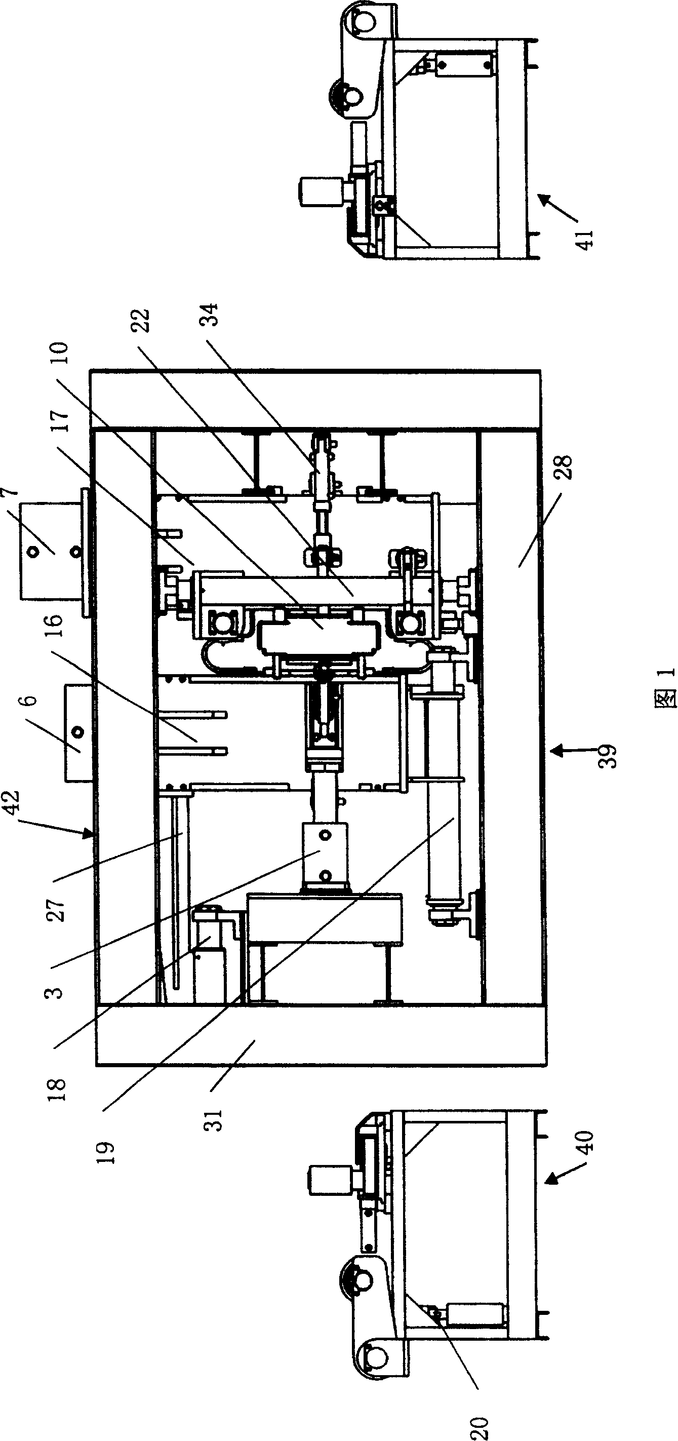
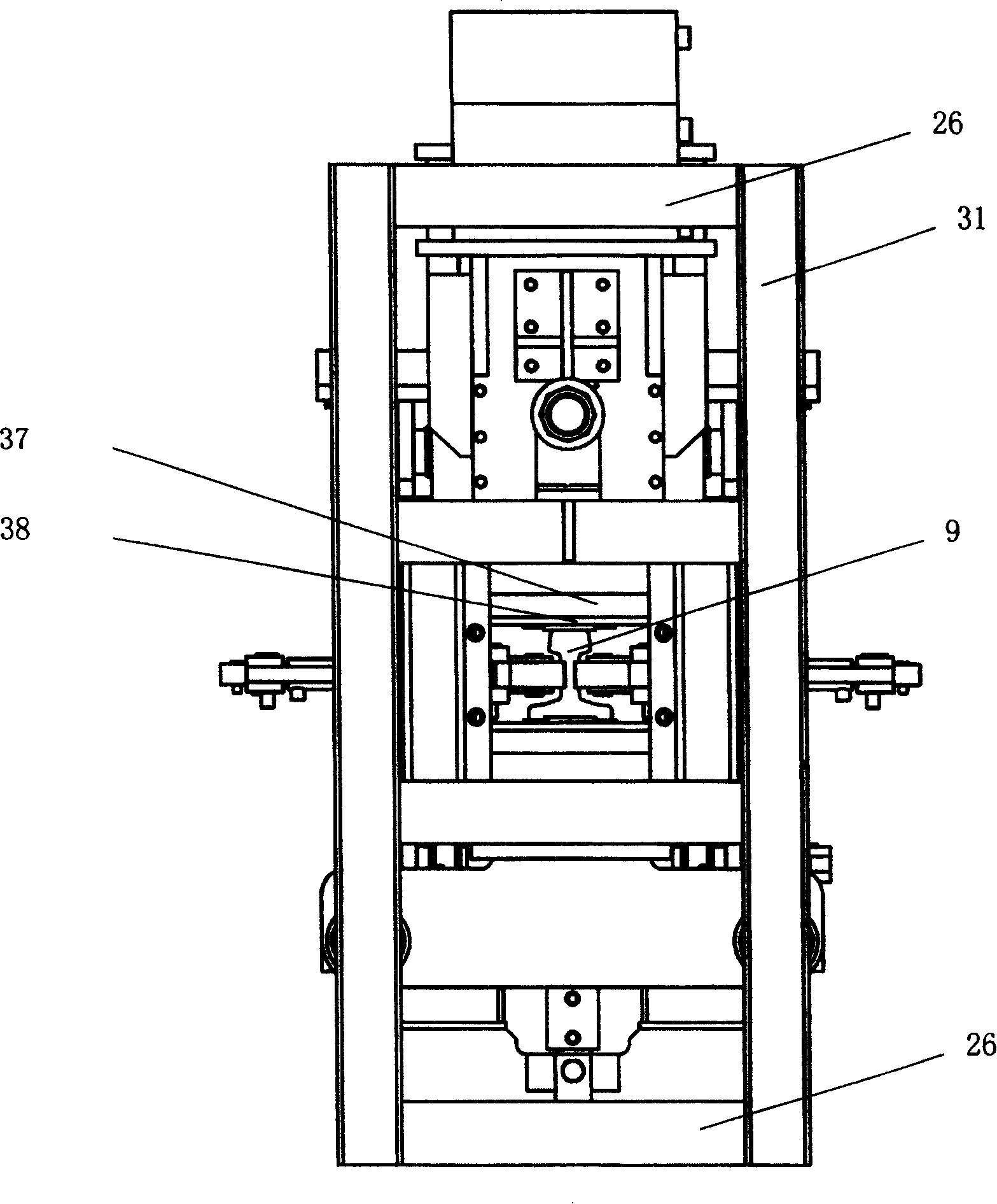
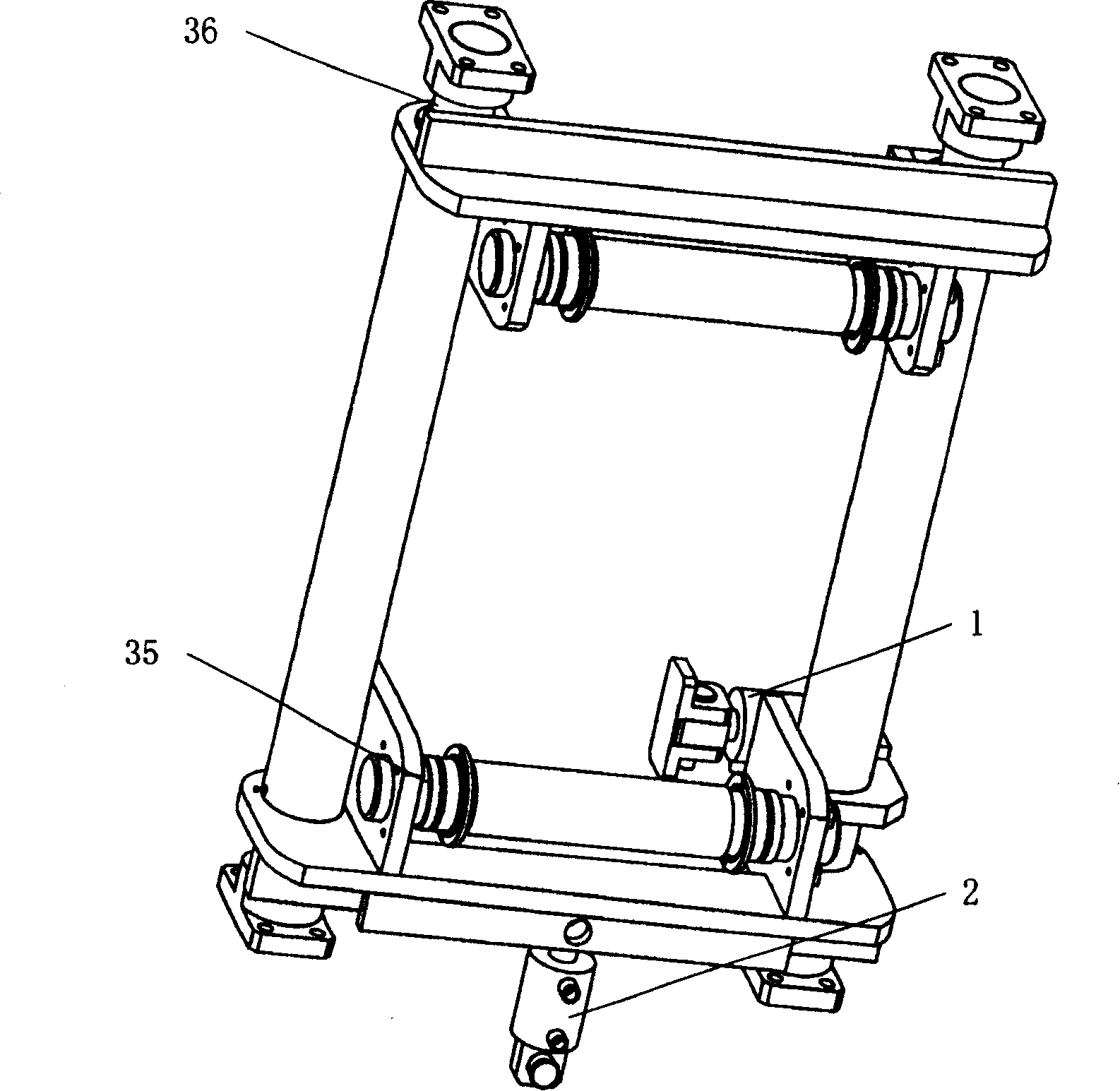
[0029] Figure 1- Figure 5 As shown, the fixed rail flash welder of the present invention includes a main frame 39 of a frame structure and two primary counter rail frames 40, 41 ( FIG. 1 ) independent of the main frame 39 . The frame of fixed rail flash welding machine main frame 39 adopts frame structure, and frame 42 is made up of four longitudinal beams 28, four end beams 26 and four vertical beams 31. Inside the frame 42 there are a moving frame 16, a static frame 17 and a centering frame 22. The upper ends of the moving frame 16 and the static frame 17 are respectively connected to the rail clamping oil cylinder 6 of the moving frame and the rail clamping oil cylinder 7 of the static frame, and the lower end of the piston of the rail clamping oil cylinder 7 of the static frame is connected to the transformer cover 37, and the rail electrode 38 is c...


PUM


Abstract

The invention relates to a stationary rail flash welder, comprising main frame and two primary rail racks 40 and 41. The main frame rack 42 is equipped with moving rack 16, static rack 17 and centering rack 22. The moving and static rack are connected with moving rack rail clamping cylinder 6 and static rack rail clamping cylinder 7 on the upper side respectively, static rack rail clamping cylinder 7 is connected with potential transformer cover 37, and the lower part of potential transformer is connected to rail electrode 38. The moving rack 16 is connected with cradle 42vthrough supporting axis 18 and lower supporting axis 19, and the insulated heading cylinder 3 is connected with cradle 42 and moving rack 16. The horizontal centering cylinder I on right of centering rack 22 is connected with static rack 17, and vertical centering cylinder 2 is connected with cradle 42. The moving and static rack is equipped with a unit of horizontal adjusting and locating device respectively. The horizontal clamping device of primary rail racks 40 and 41 on rail bottom is drove by cylinder 21 through rack bar 30, and rack bar 30 drives two gears to rotate and locate rail in horizontal direction. The vertical location for rail is finished by lifting gearing. The invention can obviously improve welder working condition and increases welding quality.

Description

technical field [0001] The present invention relates to the equipment used for seamless line rail welding in the railway or urban rail transit industry, in particular to a fixed-type rail flashing used in rail welding factories or bases to complete the welding of fixed-length rails into hundreds of meters long rails welder. Background technique [0002] Known a kind of fixed type rail flash welding machine is the fixed type flash welding machine invented by Schlatter Company in Switzerland. Secondary rectification and rail centering mechanism. The working method is: after the rail enters the position to be welded, the rail clamping mechanism at both ends of the welding machine clamps the rail waist, the rail end is near the area, the upper and lower electrodes are closed, the electrode is connected to the rail and positioned, and the micro movement of the rail on one side Adjustment Complete the centering adjustment and then proceed to welding. The rail welding machine ad...

Claims


Application Information

Patent Timeline
Patent Type & Authority Patents(China)
IPC IPC(8): B23K11/04B23K11/36B23K37/04
Inventor 丁韦刘艳红高文会宋宏图黄辰奎王贵山
Owner BEIJING RAILWELD NEW MATERIAL TECH CO LTD
Why Eureka
Try Eureka