Hose connector

A hose connection and hose technology, which is used in hose connection devices, pipes/pipe joints/pipes, mechanical equipment, etc. The problems such as the inability to use the shower head can improve the workability, realize the manufacturing cost, and reduce the inventory management and warehouse space.

Inactive Publication Date: 2008-06-25
TOYOX CO LTD
View PDF7 Cites 1 Cited by
  • Summary
  • Abstract
  • Description
  • Claims
  • Application Information

AI Technical Summary

Problems solved by technology

[0009] However, in such conventional hose connectors, the insertion of the pressure cylinder is performed while the hose is connected to the connection cylinder, and this insertion work requires that the pressure cylinder cannot be easily detached from the hose. Forcibly moving the pressure cylinder toward the axial direction of the hose, but because the connection cylinder becomes an obstacle, the insertion operation of the pressure cylinder is difficult. At the same time, after this installation, it is necessary to move the hose or the connection cylinder to move the pressure cylinder Since it is inserted into the connection cylinder, the workability is poor, which causes the increase in manufacturing cost.
[0010] In particular, sprinklers such as sprinklers have a variety of different colors, lengths, and functions, etc., and there are also a variety of hangers (connecting cylinders) and hoses for shower heads connected to them. It becomes a large quantity, but for the existing hose connectors, hoses and connecting cylinders are installed, so it is not possible to quickly respond to various orders without stocking a large number of various types of connectors. , requiring inventory management and warehouse space, becoming a cause of rising costs
[0011] In addition, for the sprinkler head manufactured in foreign countries, there is a structure that sandwiches flat packing between the end face and the shower head hanger (connecting cylinder) to prevent water leakage, but the existing hose connector Among them, the sprinkler head is penetrated by a hanger (connecting cylinder), and there is no flat packing support surface, so it cannot be connected. Such a foreign sprinkler head cannot be used in an existing domestic hose connector.

Method used


Image

  • Hose connector
  • Hose connector
  • Hose connector

Examples


Embodiment 1

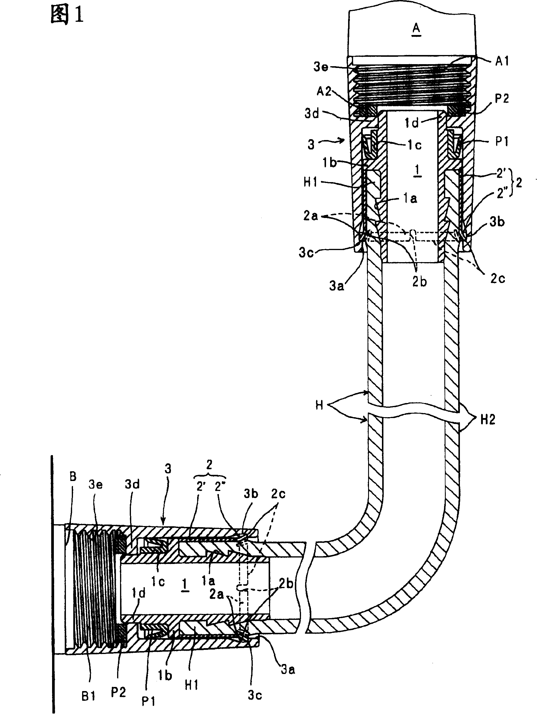
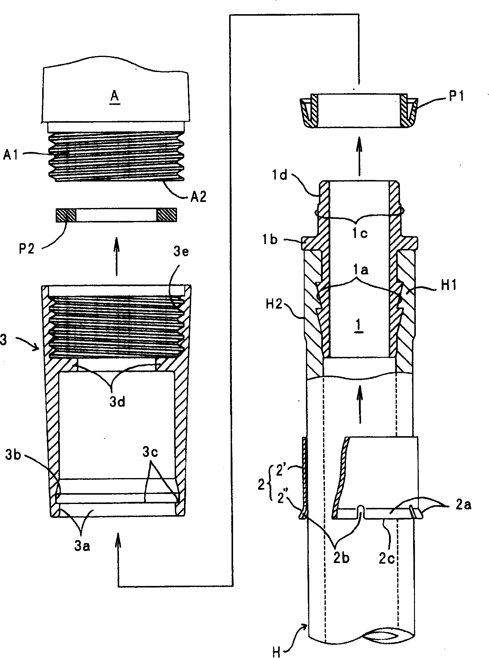
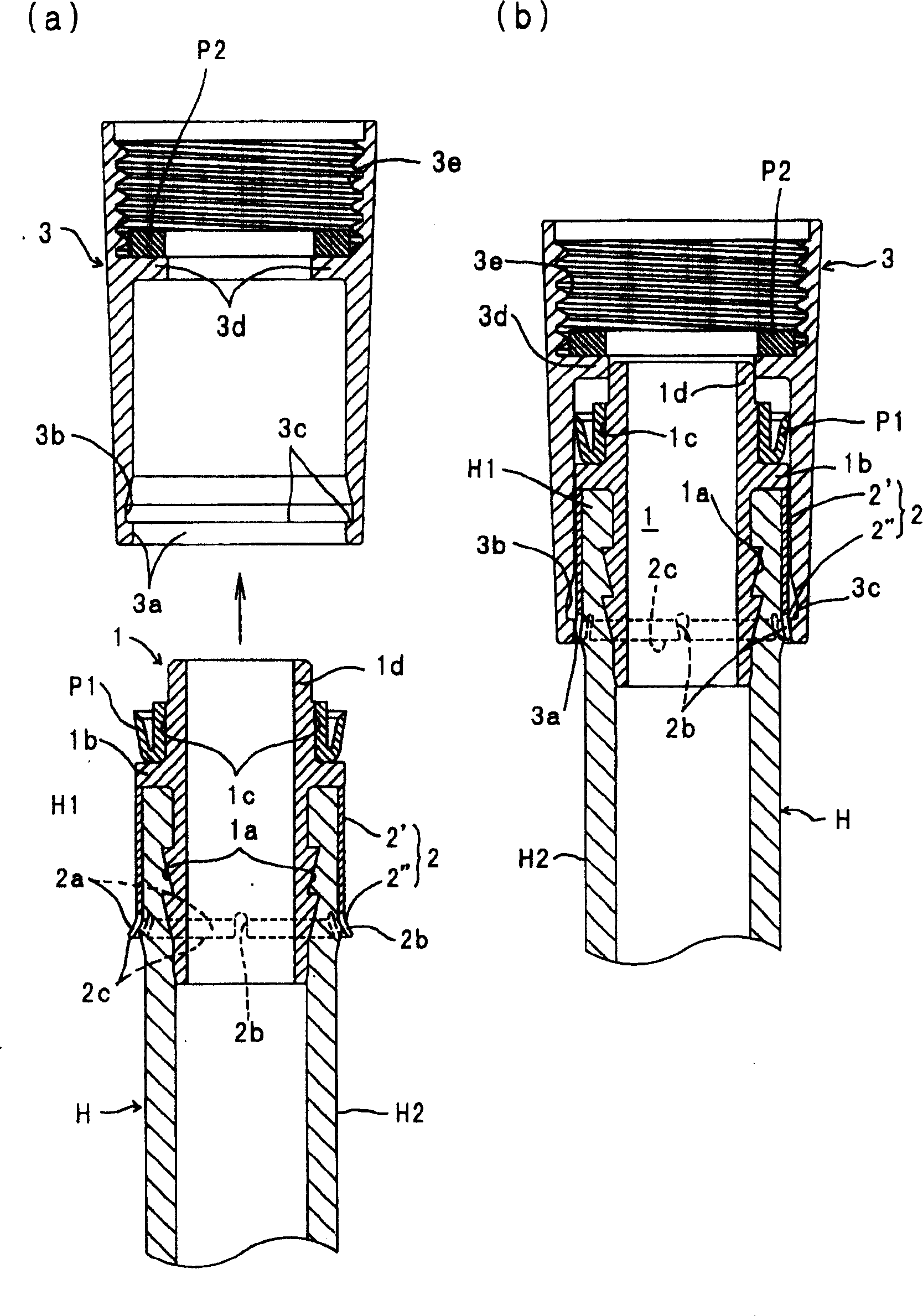
[0057] This embodiment 1 is shown in Fig. 1~ image 3 As shown, the above-mentioned pressure cylinder 2 is an integrally formed product in which the cylindrical part 2' and the elastic joint part 2" are continuously formed in the axial direction, and the base end side of these cylindrical part 2' and the elastic joint part 2" is integrally formed. Expanded diameter part 2a.

[0058] In the example shown in the figure, such as figure 2 As shown, a plurality (six) of space portions 2 b for diameter reduction are provided at equal intervals in the circumferential direction on the proximal edge 2 c of the diameter expansion portion 2 a.

[0059] In addition, by allowing the inner peripheral surface of the packing support protrusion 3d of the connecting cylinder 3 to be rotatably inserted through the outer peripheral surface of the joint portion 1d of the pipe joint 1 , the pipe joint 1 is prevented from moving against the connecting cylinder 3 . shaking.

[0060] Next, the conn...

Embodiment 2

[0070] The embodiment 2 as Figure 4 ~ Figure 5 As shown, the above-mentioned pressure cylinder 2 is an assembled molded part, and a cylindrical cylindrical part 2' and a substantially cylindrical elastic joint part 2" protruding from the cylindrical part only from the enlarged diameter part 2a are respectively formed. The outer side of the cylindrical part 2' can not move axially and fix the elastic joint part 2 ", thereby disposing the fixed elastic joint part 2 " on the radially outer side of the cylindrical part 2', these are the same as the above-mentioned Figs. image 3 The illustrated embodiment 1 is different, and the other configurations are the same as those shown in Figs. image 3 Example 1 shown is the same.

[0071] As a method of manufacturing such a press cylinder 2, such as Figure 5 (a) As shown in (b), at first, only one of the two openings of the cylindrical part 2' is processed for diameter expansion, and the diameter expansion is formed in advance by ins...

Embodiment 3

[0077] The present embodiment 3 such as Figure 6 ~ Figure 7 As shown, the above-mentioned pressing cylinder 2 is an integral molded part in which the base end side of the cylindrical cylindrical part 2' is folded back and the elastic joint part 2" is arranged and fixed on the radially outer side of the cylindrical part 2'. With the above figure 1~ image 3 The illustrated embodiment 1 is different, and the other configurations are the same as those shown in Figs. image 3 Example 1 shown is the same.

[0078] As a method of manufacturing such a press cylinder 2, such as Figure 7 As shown in (a) to (c), at first, for example, punch out the base end portion of the cylindrical portion 2′ by punching, etc., to form the slit-shaped diameter-reducing space portion 2b, and then turn the base end portion by folding back. The expanded diameter portion 2a of the elastic engagement portion 2" is integrally formed by being folded back along the outer peripheral surface of the cylindr...


PUM


Abstract

PROBLEM TO BE SOLVED: To perform insertion and attachment of a pressing cylinder to a hose and assembly to a connection cylindrical body in separate processes by separating them from each other.

Description

technical field [0001] The present invention relates to a hose connection for use in connecting a hose to water spray appliances such as shower heads and supply fittings such as water supply taps or mixer taps. [0002] In detail, it relates to a hose connector having a cylinder mounted on the connection ends of the hose and a connection cylinder inserted into the hose connection ends and the cylinder so that the cylinder When the hose axially contacts the inner surface of the connecting cylinder, it can be freely rotated and prevented from coming off. Background technique [0003] In the past, as such a hose connector, there has been a structure in which the hose is sequentially inserted through a connecting cylinder (nut for connecting an appliance) and a pressure cylinder (caulking cylinder), and the joint of the pipe joint is After the bamboo shoot-shaped part is inserted into the inner circumference of the protruding hose connection end, a pressure cylinder (caulking c...

Claims


Application Information

Patent Timeline
Patent Type & Authority Patents(China)
IPC IPC(8): F16L33/22
Inventor 堀一耕二
Owner TOYOX CO LTD
Why Eureka
Try Eureka