Check patentability & draft patents in minutes with Patsnap Eureka AI!

Hollow soft drill and its manufacturing method

A hollow and soft drill technology, applied in the direction of the fixer, can solve the problem of inappropriate hollow bone drill, and achieve a simple and effective processing method.

Inactive Publication Date: 2008-07-02
SHANGHAI SECOND POLYTECHNIC UNIVERSITY
View PDF8 Cites 0 Cited by
  • Summary
  • Abstract
  • Description
  • Claims
  • Application Information

AI Technical Summary

Problems solved by technology

Since the prosthesis sometimes breaks, if the prosthesis stem needs to be removed from the medullary cavity and a new prosthesis needs to be installed, it is obviously inappropriate to use the above-mentioned rigid hollow bone drill

Method used


Image

  • Hollow soft drill and its manufacturing method
  • Hollow soft drill and its manufacturing method

Examples


Embodiment Construction

[0009] according to figure 1 As shown, the present invention is made up of drill shank 1, hollow sleeve 4 and cutting edge 2, drill shank 1 is connected with the upper end of hollow sleeve 4 by pin 3, cutting edge 2 is connected with the lower end of hollow sleeve 4, and hollow sleeve 4 is made up of several groups Composed of 5 links.

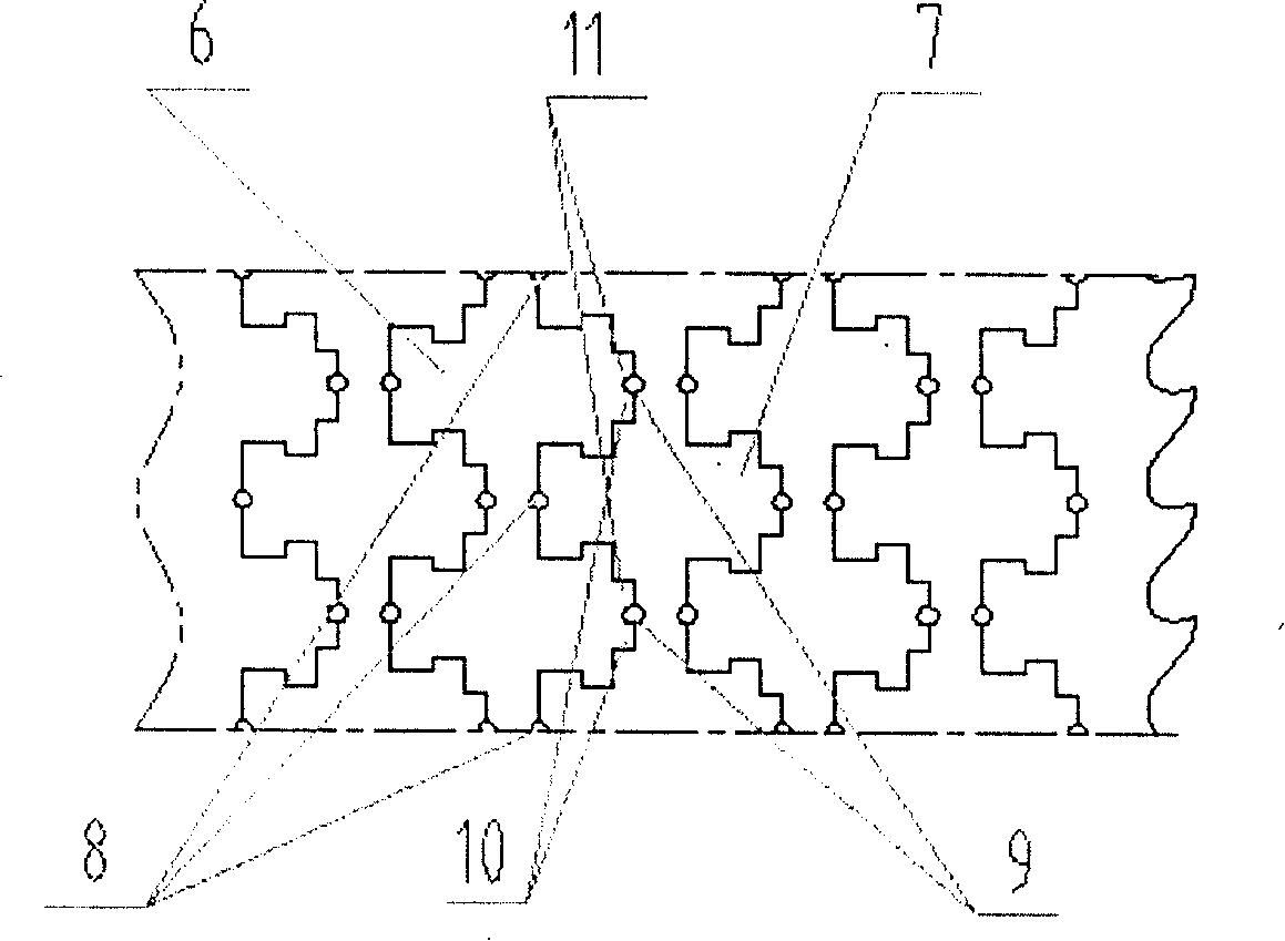
[0010] according to figure 2 As shown, the hollow sleeve is composed of several groups of chain links, and each group of chain links is composed of two upper and lower horizontal short sections that are not connected, and the middle is long and connected, which is like the word "King". The upper group of chain links 6 and the lower group of chain links 7 are 90 degrees to each other, so that the next cross of the upper chain link 6 is embedded in the space between the upper two crosses of the lower chain link 7, so that the upper and lower chain links 6, 7 are connected to each other. There is a shoulder 10 in the next horizontal of each "W...


PUM


Abstract

The present invention relates to a hollow soft drill and its production method. In particular, it relates to a hollow soft drill for taking out prosthesis holder from marrow cavity and its making method. Said hollow soft drill is formed from drillstock, hollow cover and cutting edge. Besides, said invention also provides the concrete steps of its making method.

Description

Technical field: [0001] The invention relates to a hollow soft drill and a manufacturing method thereof, in particular to a hollow soft drill for taking out a prosthesis stem from a medullary cavity and a manufacturing method thereof. technical background: [0002] In medical operations, hollow bone drills are often used to remove foreign bodies such as broken nails in the femur, such as the hollow bone drills involved in CN86203850 and ZL97213490.5. This type of hollow bone drill consists of three parts: a drill handle, a hollow sleeve and a cutting edge , The drill shank, hollow sleeve and cutting edge are concentric and rigid. In medical operations, when a patient needs to install an artificial prosthesis in the medullary cavity due to disease, in order to ensure the stability of the prosthesis installation, a prosthesis stem with the same curvature as the bone medullary cavity is installed in the medullary cavity, and the Between the cavity and the prosthetic stem, bone...

Claims


Application Information

Patent Timeline
Patent Type & Authority Patents(China)
IPC IPC(8): A61B17/92
Inventor 王钧
Owner SHANGHAI SECOND POLYTECHNIC UNIVERSITY
Features
  • R&D
  • Intellectual Property
  • Life Sciences
  • Materials
  • Tech Scout
  • Unparalleled Data Quality
  • Higher Quality Content
  • 60% Fewer Hallucinations
Learn More