Light-emitting diode module

A technology of light emitting diodes and curved surfaces, applied in electrical components, electrical solid devices, circuits, etc., can solve the problem of light being unable to diverge, and achieve the effect of avoiding bright spots, extending angular energy distribution, and reducing the number of uses and manufacturing costs.

Inactive Publication Date: 2008-07-02
AU OPTRONICS CORP
View PDF4 Cites 0 Cited by
  • Summary
  • Abstract
  • Description
  • Claims
  • Application Information

AI Technical Summary

Problems solved by technology

[0006] Therefore, the main purpose of the present invention is to provide a light-emitting diode module to improve the problem that light cannot be diverged due to the design of multiple light sources sharing the same curved surface in the existing light-emitting diode module

Method used


Image

  • Light-emitting diode module
  • Light-emitting diode module
  • Light-emitting diode module

Examples


Embodiment Construction

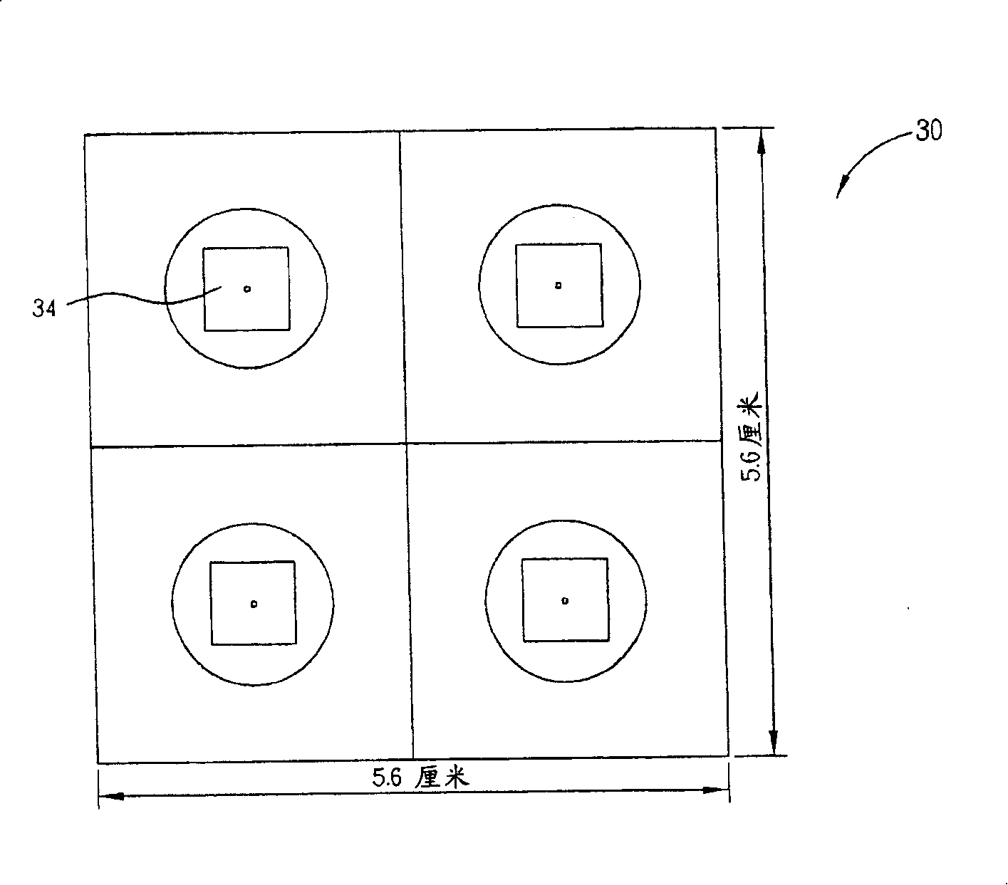
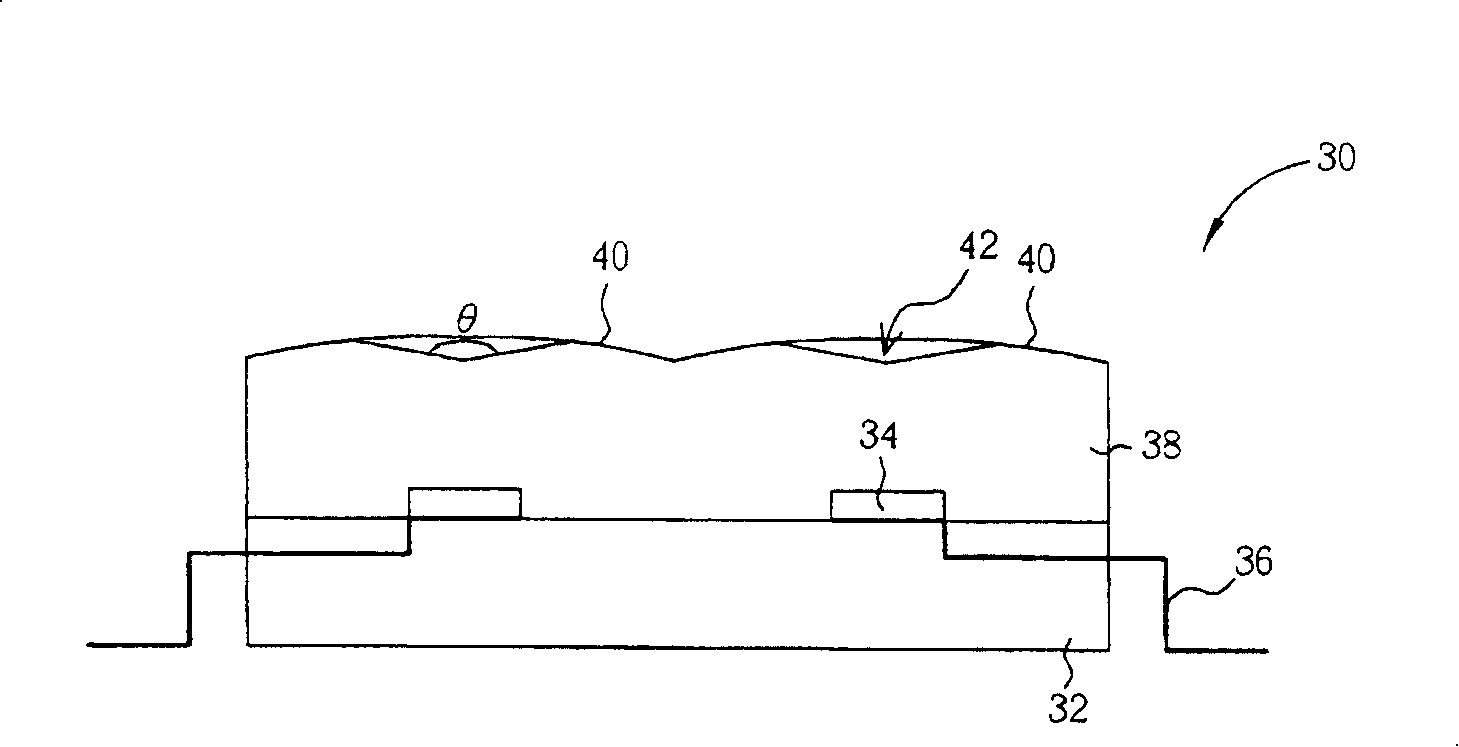
[0030] Please refer to figure 2 and image 3 , figure 2 is a top view of the light emitting diode module 30 of the preferred embodiment of the present invention, and image 3 for figure 2 A side view of the LED module 30. Such as figure 2 As shown, the light-emitting diode module 30 is composed of four light-emitting diodes 34 arranged in an array, and the light-emitting diodes 34 may be composed of red light-emitting diodes, green light-emitting diodes, blue light-emitting diodes, white light-emitting diodes or other colored light-emitting diodes group. However, it is not limited to this arrangement, and the present invention can configure different numbers, colors and arrangements of the light emitting diodes 34 according to the requirements of the product, all of which should fall within the scope of the present invention.

[0031] Such as image 3 As shown, the LED module 30 includes a substrate 32, a plurality of LEDs 34 disposed on the substrate 32, a lead fra...


PUM


Abstract

The present invention discloses light emitting diode module. It includes base material, plurality of light emitting diode and plurality of lens, wherein said light emitting diode located on said base material surface, said lens set on said base material and covering said light emitting diode, each upper surface of lens all having curved face respectively corresponded to each light emitting diode.

Description

technical field [0001] The invention relates to a light emitting diode module. Background technique [0002] With the increasing development of the information industry, digital tools such as mobile phones, digital cameras, digital video cameras, notebook computers, and desktop computers are all developing in a more convenient, multi-functional and beautiful direction, and in recent years, the display of most digital tools The screens are all liquid crystal display panels (LCD panel) as the mainstream. However, since the liquid crystal display panel itself does not have the function of emitting light, a backlight unit (backlight unit) must be provided under the liquid crystal display panel to provide the surface light source required by the liquid crystal display panel, so that the liquid crystal display can achieve a self-luminous display effect. . At the same time, through the backlight module, the liquid crystal panel can obtain sufficient brightness and contrast, and t...

Claims


Application Information

Patent Timeline
Patent Type & Authority Patents(China)
IPC IPC(8): H01L25/00H01L25/075
Inventor 蔡卲瑜王誌麟黄志濠彭赐光
Owner AU OPTRONICS CORP
Why Eureka
Try Eureka