Brightness detection method

A technology of brightness detection and brightness, which is applied in photometry, measuring devices, optical radiation measurement, etc., can solve the problems of on-site operations that are not suitable for mass production, attenuation of light brightness values, inconsistent judgment results, etc., to improve detection speed and detection accuracy, prevent the interference of external light, and avoid the effect of inconsistent results

Inactive Publication Date: 2008-07-16
ASIA OPTICAL CO INC
View PDF5 Cites 0 Cited by
  • Summary
  • Abstract
  • Description
  • Claims
  • Application Information

AI Technical Summary

Problems solved by technology

[0002] In laser ranging telescopes, light emitting diodes (Light Emitting Diode, LED) or organic light emitting diodes (Organic Light Emitting Diode, OLED) are usually configured to display crosshairs and ranging values, and the brightness values ​​of LEDs or OLEDs are generally It is provided by the manufacturer, but the information provided by the manufacturer is not necessarily accurate, because the crosshair and distance measurement value projected by the LED or OLED need to pass through the focusing lens, prism group and eyepiece group in the telescope. The lens can only be observed by the human eye. Since the above-mentioned lens has the function of absorbing and reflecting light, the brightness value of the light that finally reaches the human eye must be attenuated a lot, that is, the brightness of the light observed by the human eye will be different from that of LED or There are differences in the original luminance value of OLED, which makes it difficult to use the original luminance value of the original light-emitting display unit as a basis for judging whether the final product meets the standard
If human eyes are used to directly judge its brightness, the judgment results will be inconsistent and inaccurate due to the sensory differences of human eyes.
In order to quantify the luminance of the luminous display unit reaching the human eye and make it conform to objective luminance standards, some people have tried to use ordinary illuminometers or spectroradiometers to measure, but because the laser ranging telescope The light area projected by LED or OLED is very small, it is difficult to measure it, and these measurement equipment are very expensive and not suitable for high-volume production field operations

Method used


Image

  • Brightness detection method
  • Brightness detection method
  • Brightness detection method

Examples


Embodiment Construction

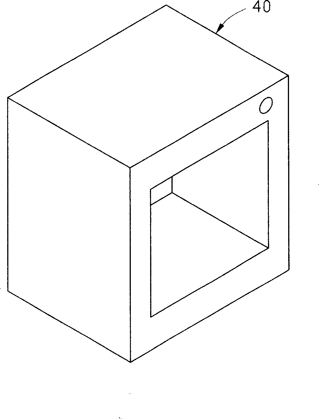
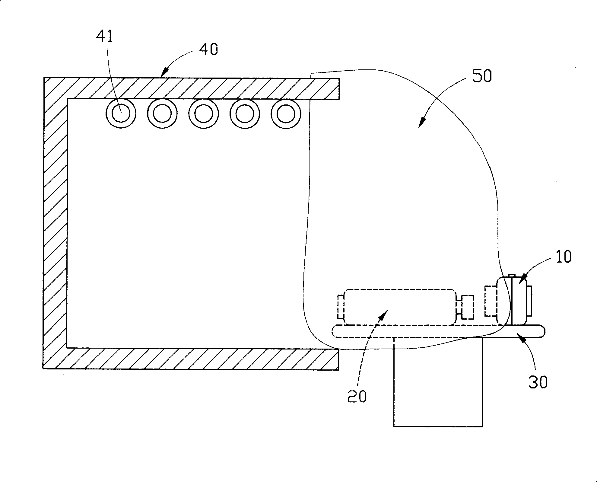
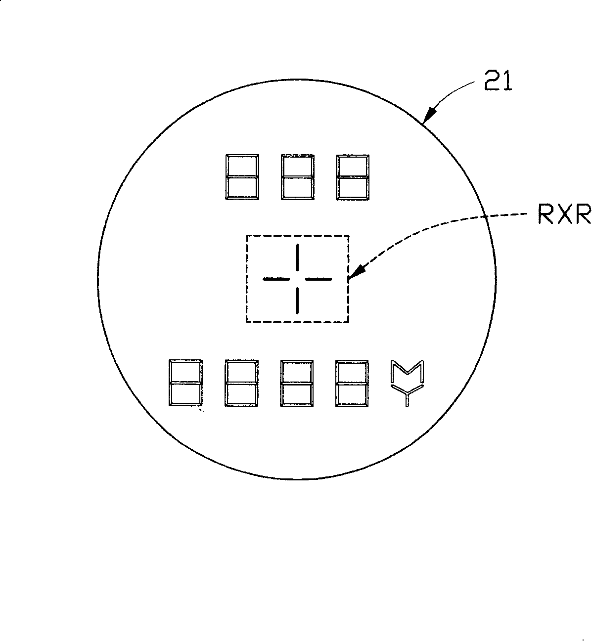
[0022] In this embodiment, we will take the binocular laser ranging telescope as an example to introduce the brightness detector and its detection method of the present invention. In the binocular laser ranging telescope, there is also the same problem as described in the prior art, that is, the brightness of the crosshairs and ranging values ​​​​observed by the human eye will be lower due to the absorption and reflection of the lens on the light. It will be different from the brightness of the original light emitted by the OLED. Therefore, after the binocular laser ranging telescope is manufactured, it is necessary to re-test the brightness of the OLED light that can reach the human eye, so as to confirm whether the display brightness meets the requirements. . The luminance detector of the present invention and its detection method are to quantify the luminance of the light reaching the human eye, and formulate a limit value to judge whether the luminance value has reached th...


PUM


Abstract

The invention discloses a luminance detector and method, which comprises the following parts: focal unit, sensing unit, disposing unit and display unit. The detecting method comprises the following steps: providing a fixing temperature colour to analog the outdoor temperature colour light; placing the luminance detector and detected laser distant telescope on the platform; covering the laser distant telescope and luminance detector through opaque lid to avoid the interference of outside ray; supplying the needed ray for laser distant telescope through the fixing temperature colour; detecting the distance through laser distant telescope; picking the cross line and distant value luminance of luminous unit through luminance detector; displaying the disposed and calculated measured value on the display unit of luminance detector.

Description

【Technical field】 [0001] The invention relates to a brightness detection method, in particular to a brightness detection method for measuring the light quantity of a light-emitting device with a light-emitting display unit. 【Background technique】 [0002] In laser ranging telescopes, light emitting diodes (Light Emitting Diode, LED) or organic light emitting diodes (Organic Light Emitting Diode, OLED) are usually configured to display crosshairs and ranging values, and the brightness values ​​of LEDs or OLEDs are generally It is provided by the manufacturer, but the information provided by the manufacturer is not necessarily accurate, because the crosshair and distance measurement value projected by the LED or OLED need to pass through the focusing lens, prism group and eyepiece group in the telescope. The lens can only be observed by the human eye. Since the above-mentioned lens has the function of absorbing and reflecting light, the brightness value of the light that final...

Claims


Application Information

Patent Timeline
Patent Type & Authority Patents(China)
IPC IPC(8): G01J1/42G01J1/00
Inventor 王琮玮杨士贤
Owner ASIA OPTICAL CO INC
Why Eureka
Try Eureka