Optical information recording apparatus

A recording device and optical information technology, applied in the direction of optical record carrier, optical recording system, information storage, etc., can solve the problems of insufficient number of rewritable times of optical discs, insufficient effective use of PCA area, etc., to achieve increased rewritability The effect of rewriting times, increasing the number of times, and reducing deterioration

Active Publication Date: 2008-07-23
JVC KENWOOD CORP
View PDF9 Cites 0 Cited by
  • Summary
  • Abstract
  • Description
  • Claims
  • Application Information

AI Technical Summary

Problems solved by technology

[0024] In addition, there is also the following problem. In the prior art, OPC that takes into account the degradation of the PCA area is not necessarily performed, and the effective use of the PCA area is not sufficient. As a result, the number of rewritable times of the optical disc cannot be obtained sufficient times.

Method used


Image

  • Optical information recording apparatus
  • Optical information recording apparatus
  • Optical information recording apparatus

Examples


Embodiment 1

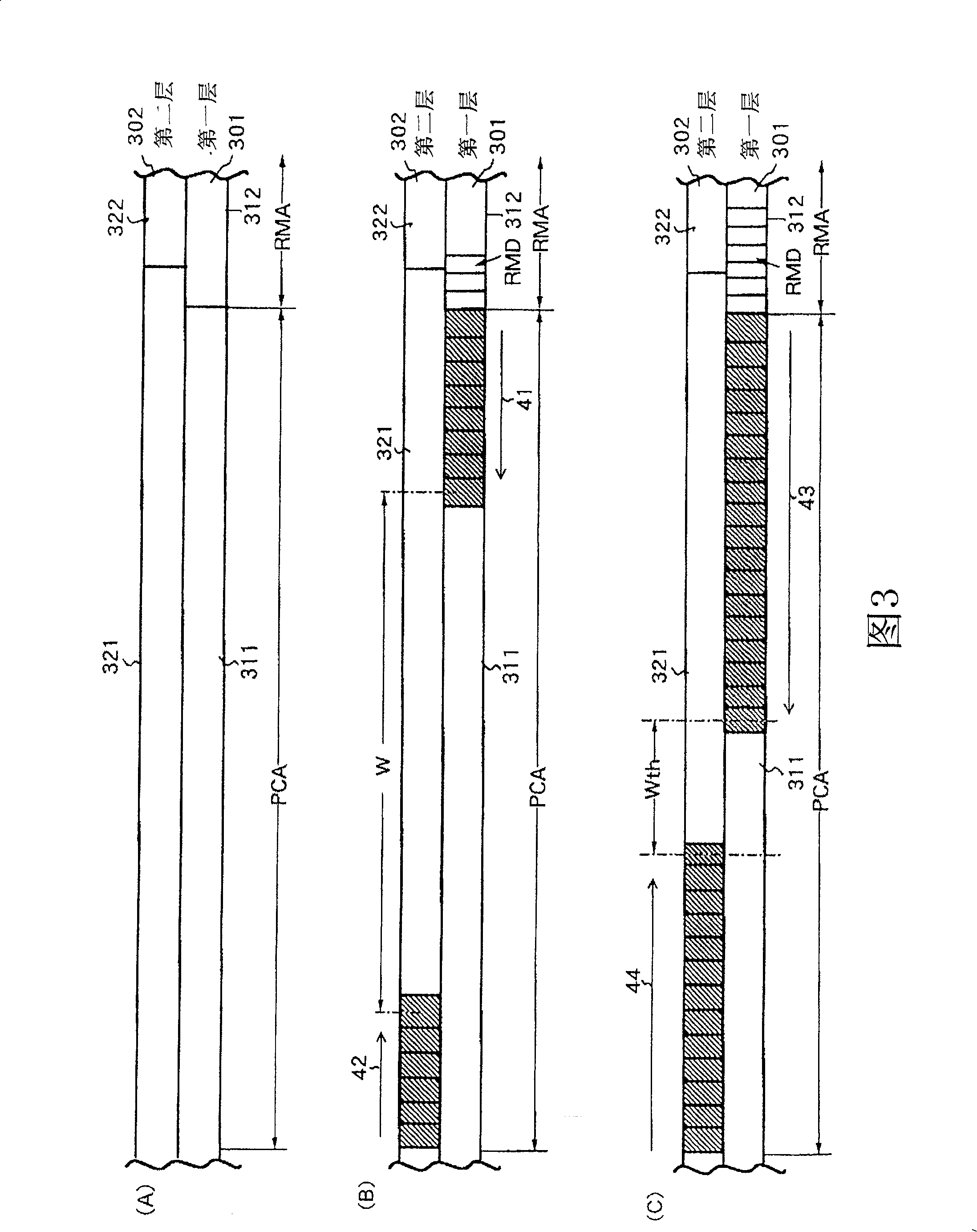
[0060] FIG. 3 shows the R information area of ​​a single-sided double-layer DVD-RW disc 30 for explaining the test writing operation of the first embodiment of the optical information recording apparatus of the present invention. In this figure, the same reference numerals are assigned to the same components as in FIG. 13 . FIG. 3(A) shows the state of the R information area after DC deletion is performed on the initial R information area or the entire PCA area.

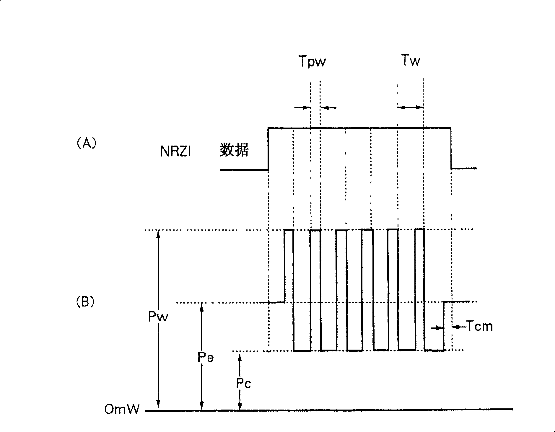
[0061] FIG. 3(B) shows the state of the R information area after OPC processing has been performed several times on both the first recording layer 301 and the second recording layer 302 . And in an OPC transaction, such as Figure 4 As shown in (A), test writing was performed by changing the recording power in 10 steps. The trial-written small area is reproduced to obtain a reproduced RF signal, and a known evaluation scale β is obtained from the reproduced RF signal. This β corresponds to the symmetry of the uppe...

Embodiment 2

[0090] Next, Embodiment 2 of the present invention will be described. In Embodiment 1, the DC deletion of the PCA area is to delete the areas in the first layer and the second layer where trial writing was performed. In this case, in the first-layer PCA area 311 , the number of cycles of trial writing→DC erasure in the small area on the outermost periphery is greater than that in the small area near the center. In the second-layer PCA region, the number of periods in the small region on the innermost peripheral side is larger than that near the center. As a result, the small area on the outermost peripheral side of the PCA region 311 of the first layer and the innermost peripheral side of the PCA region 321 of the second layer deteriorates earlier than near the center.

[0091] Fig. 6 shows the form of the PCA area in this case, Fig. 6 (A) is the situation when the first layer PCA area 311 is more for trial writing, Fig. 6 (B) is the second layer PCA area 321 for more trial w...

Embodiment 3

[0102] Next, Embodiment 3 of the present invention will be described. In this embodiment, the purpose is to use the entire PCA area for OPC processing and prevent degradation of the PCA area.

[0103] FIG. 8 shows the R information area of ​​a single-sided double-layer DVD-RW disc 30 for explaining the test writing operation of the third embodiment of the optical information recording apparatus of the present invention. In this figure, the same components as those in FIG. 13 are given the same reference numerals. FIG. 8(A) shows the state of the R information area after performing DC deletion on the initial R information area or the entire PCA area.

[0104] Fig. 8 (B) shows that OPC process is carried out to the first layer PCA area 311, obtain optimum recording power, and use this optimum recording power to start recording the band sector of predetermined capacity from the innermost peripheral side of the first layer PCA area 311 The form of numbered dummy data. In FIG. 8...


PUM


Abstract

In a rewritable optical disk, effective use of a PCA area is inadequate, although effective use of the area is necessary, since securable area as a PCA area for getting the optimal recording power is limited and as a result, rewritable frequency is not sufficient. The distance W between last time used areas of a PCA area 311 of a first layer and a PCA area 321 of a second layer are calculated as above, and compared with a set threshold Wth. As a result of comparison, when the computed distance W is equal to threshold Wth as (C), or when the computed distance W is determined to be smaller than the distance Wth, DC erasure of PCA areas 311 and 321 are performed at that time. Thereby in terms of each of PCA areas 311 and 321, the small areas used for test writing are not inclined toward specific small areas and can be used uniformly. Therefore, the frequency of OPC operation can be increased until the degradation of PCA areas 311 and 321.

Description

technical field [0001] The present invention relates to an optical information recording device, in particular to the following optical information recording device: in order to obtain the optimum Recording power, and test writing is performed in the test writing area of ​​the optical information recording medium. Background technique [0002] DVD-R discs, which are write-once discs based on the DVD (Digital Versatile Disc) standard, and DVD-RW discs, which are rewritable discs, are now widely used. Fig. 10 is a diagram schematically showing a cross-sectional structure of a DVD-R disc or DVD-RW disc having only one recording layer. In this figure, the disk 100 is divided from the inner circumference to the outer circumference into: a power calibration area (Power Calibration Area: PCA) 101, a recording management area (Recording Management Area: RMA) 102, a lead-in area (Lead-In) 103, a data area (Data Area) 104, and a lead-out area (Lead-Out) 105. [0003] The PCA area 1...

Claims


Application Information

Patent Timeline
Patent Type & Authority Patents(China)
IPC IPC(8): G11B7/0045G11B7/007
CPCG11B7/1267G11B7/00736G11B7/00458G11B7/24038
Inventor 寺西康彦
Owner JVC KENWOOD CORP
Why Eureka
Try Eureka