Processing chamber and processing device

A processing device and processing chamber technology, applied in electrical components, semiconductor/solid-state device manufacturing, circuits, etc., to achieve the effects of restraining the expansion of the floor space, restraining the expansion of the external size, and reducing the cost burden

Inactive Publication Date: 2008-07-23
TOKYO ELECTRON LTD
View PDF10 Cites 0 Cited by
  • Summary
  • Abstract
  • Description
  • Claims
  • Application Information

AI Technical Summary

Problems solved by technology

However, since this patent document 1 does not attempt to reduce the size and weight of each processing chamber itself, it cannot be said to be a fundamental solution.

Method used


Image

  • Processing chamber and processing device
  • Processing chamber and processing device
  • Processing chamber and processing device

Examples


Embodiment Construction

[0037] Preferred embodiments of the present invention will be described below with reference to the drawings.

[0038] Here, a case where the processing apparatus of the present invention is used as a multi-chamber type vacuum processing system used for etching a glass substrate for FPD will be described.

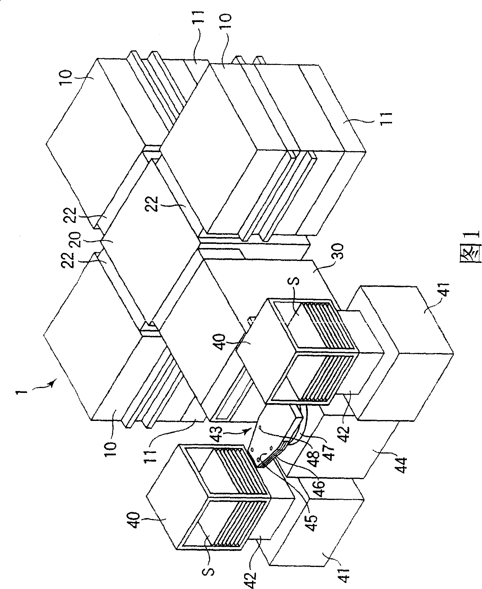
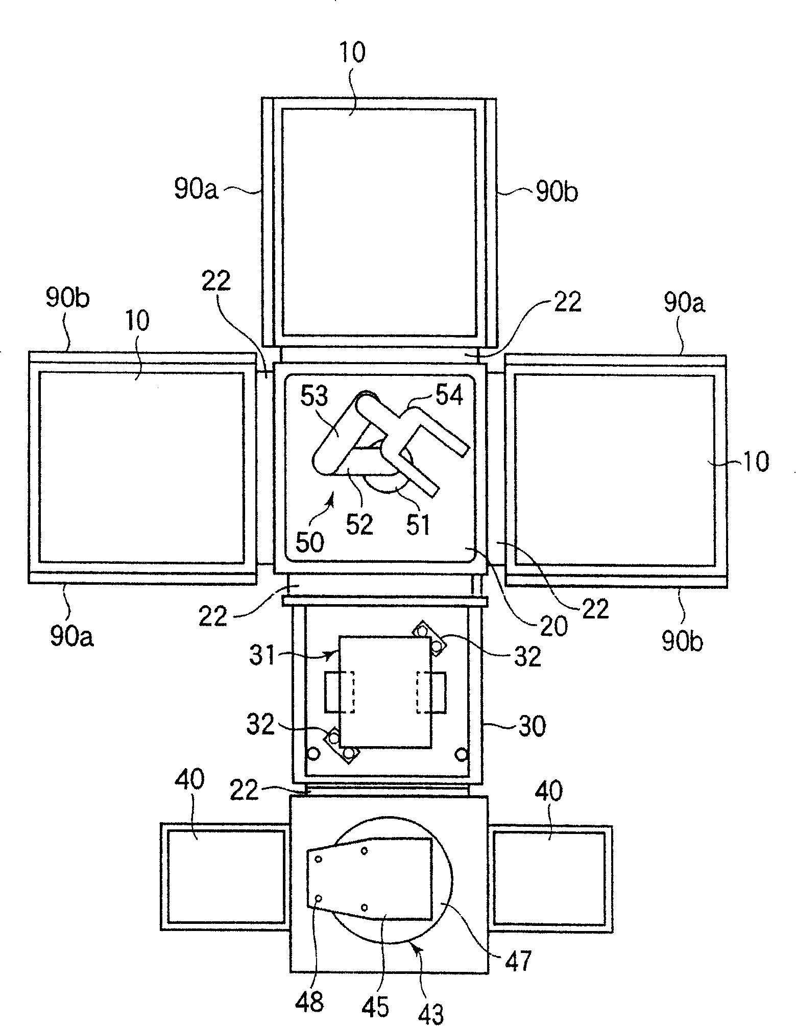
[0039] FIG. 1 is a perspective view showing a rough outline of the vacuum processing system, figure 2 is a horizontal sectional view showing its interior. Additionally, in Figure 1 and figure 2 , details are omitted from the illustration.

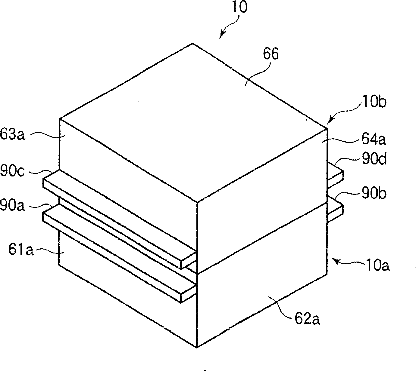
[0040] In this vacuum processing system 1 , a transfer chamber 20 and a load lock chamber 30 are provided in a continuous manner at the center thereof. Around the transfer chamber 20, three vacuum chambers 10 are arranged. Each vacuum chamber 10 is placed on a support table 11 . Between the transfer chamber 20 and the load lock chamber 30, between the transfer chamber 20 and each vacuum chamber 10, and at the opening where the load ...


PUM


Abstract

The object or this invention is to suppress expansion of the external dimension and to reduce the weight without increasing the dimensions inside a treatment chamber. The wall thickness L1 of longitudinal side walls 61a, 61b of a body 10a of a vacuum chamber 10 is smaller than the wall thickness L2 of side walls 62a, 62b, and the wall thickness of upper side walls 63a, 63b of a lid 10b is smaller than the wall thickness of upper side walls 64a, 64b. During the use, reinforcing plates 90a-90d are attachably / detachably and externally attached in order to supplement the strength of the side walls 61a, 61b and the upper side walls 64a, 64b.

Description

technical field [0001] The present invention relates to a processing chamber and a processing device, and more particularly to a large-scale processing chamber and a processing device used for substrate processing in the manufacturing process of a flat panel display (FPD) or the like. Background technique [0002] In the manufacturing process of FPD, a large rectangular glass substrate with a side length of more than 2 m is accommodated in a processing chamber and various processes are performed. In recent years, along with the increase in the size of the glass substrate, the size of the processing chamber itself has also increased, and its weight has also increased. Especially in a vacuum chamber that processes large glass substrates in a vacuum state, it is necessary to ensure that the interior of the processing chamber made of metal such as aluminum has sufficient strength to withstand atmospheric pressure in a vacuum state, and the wall thickness of the chamber must be s...

Claims


Application Information

Patent Timeline
Patent Type & Authority Patents(China)
IPC IPC(8): H01L21/00H01L21/67
CPCH01L21/67069H01L21/6719H01L21/67742
Inventor 天野健次
Owner TOKYO ELECTRON LTD
Why Eureka
Try Eureka