Cooling device for high power laser metal pumping cavity

A technology of a cooling device and a pump cavity, applied in laser technology and its application fields, can solve the problems of high difficulty in machining, complicated mechanical assembly, reduced output power, beam quality, etc., and achieves low machining difficulty, improved stability, The effect of high sealing strength

Inactive Publication Date: 2008-08-06
SHANXI FEIHONG LASER TECH
View PDF7 Cites 0 Cited by
  • Summary
  • Abstract
  • Description
  • Claims
  • Application Information

AI Technical Summary

Problems solved by technology

This cavity type cools the working substance, the pump lamp and the reflective surface separately. The electrodes of the pump lamp are exposed outside the cooling circuit. The cooling water passes through the back of the metal reflective surface and cools the surface through heat conduction. It has a large cooling capacity and stable performance. It is quite reliable, but its disadvantage is that the same device (pump lamp, reflector) in the pump cavity is difficult to maintain consistency due to uneven cooling under the same working condition, and the uneven cooling of the device leads to the strengthening of the thermal effect of the laser, which not only reduces the output power and beam quality, but also greatly shorten the laser life
The mechanical processing is difficult and the mechanical assembly is complicated. Nowadays, the lamp-pumped high-power solid-state laser mostly adopts a single working substance and a double-pumped lamp structure, and its injected electric power is as high as 10,000 watts. existing problems

Method used


Image

  • Cooling device for high power laser metal pumping cavity
  • Cooling device for high power laser metal pumping cavity
  • Cooling device for high power laser metal pumping cavity

Examples


Embodiment Construction

[0036] Attached below Figure 1 to Figure 25 This embodiment will be described.

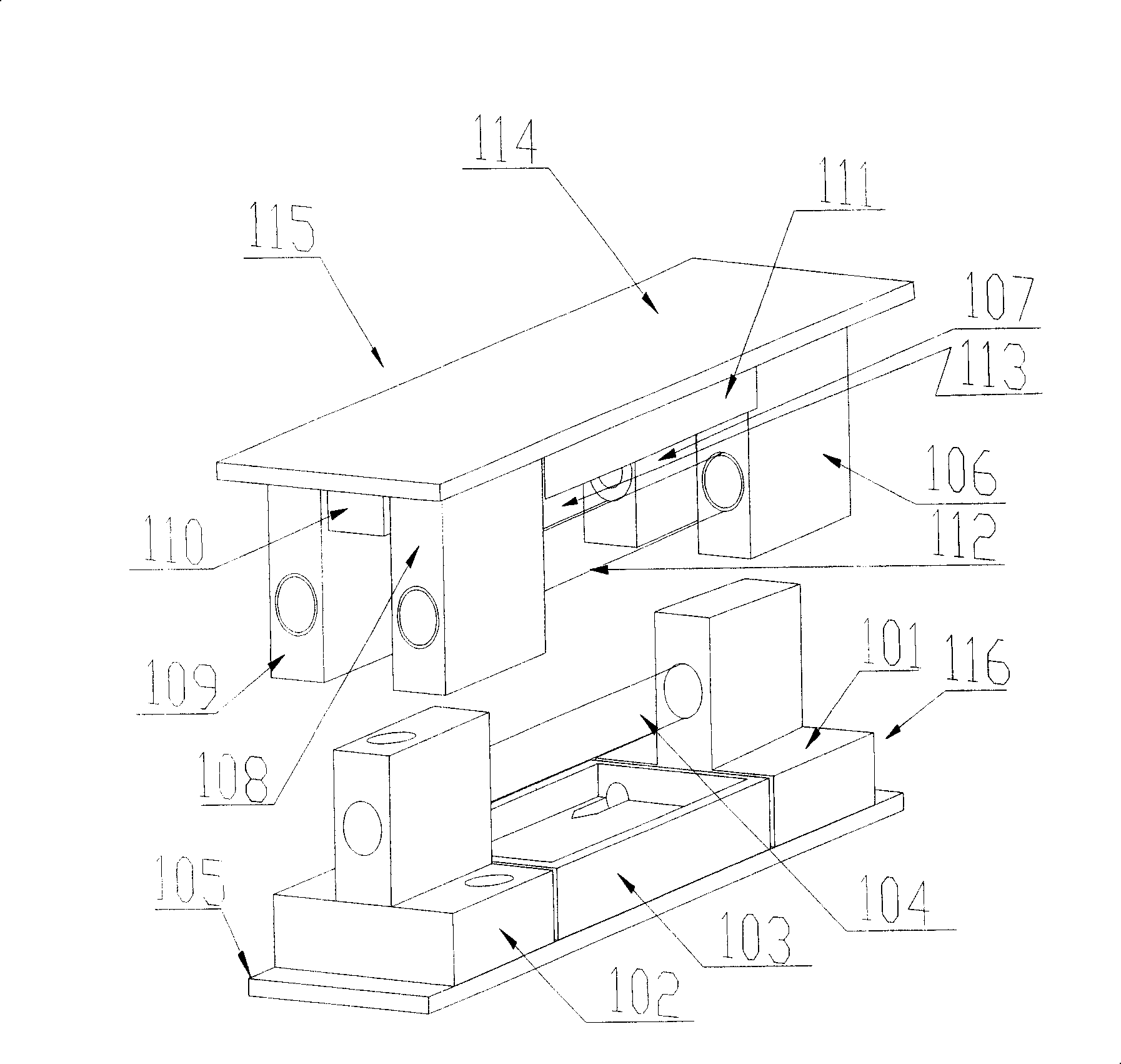
[0037] The present invention adopts the following technical solutions. In this method, according to the amount of heat absorbed by the working substance, the reflecting surface, and the pump lamp, it is determined that the cooling water first concentrates on cooling the working substance. The cooling water flowing out of the reflecting surface cools the two pump lamps respectively, and finally flows out of the cooling system.

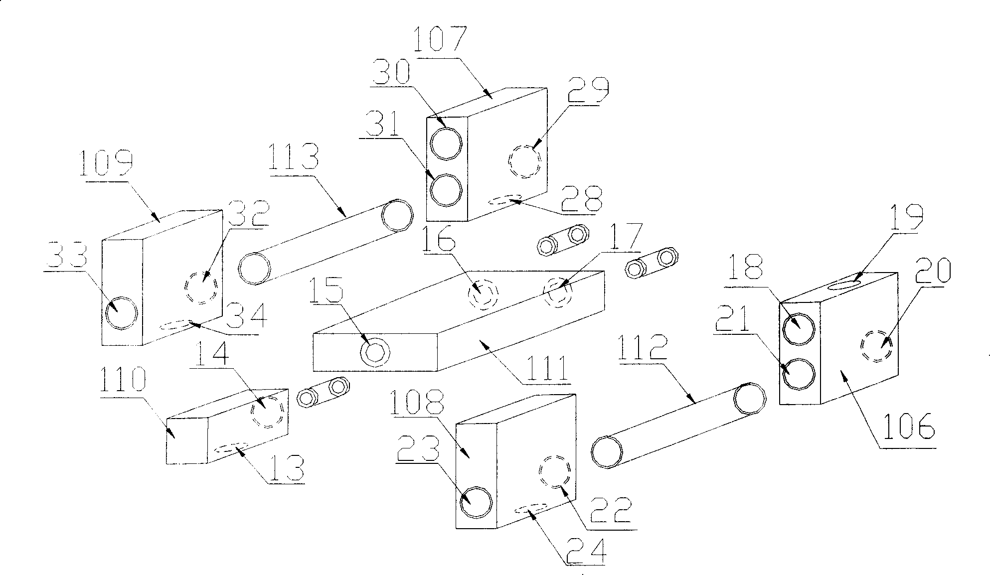
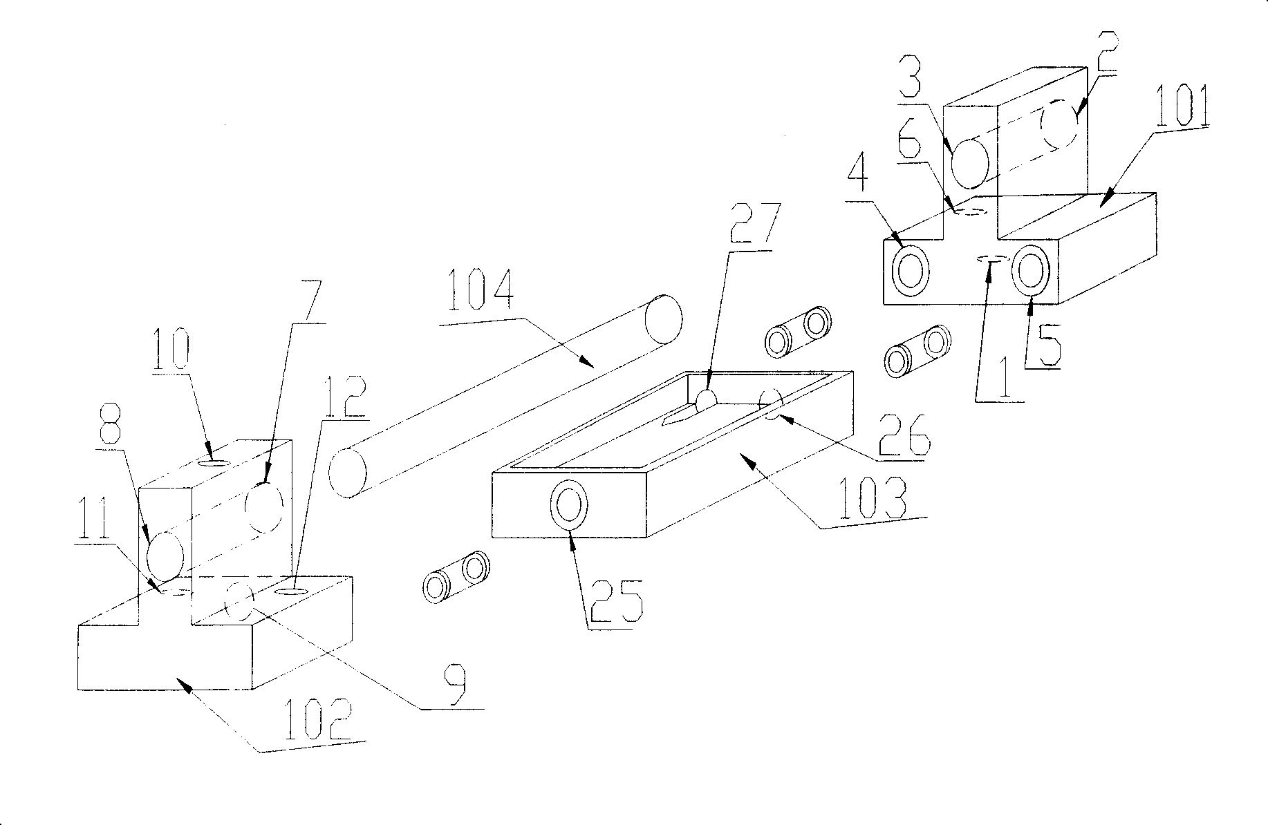
[0038] According to the cooling method of high-power solid-state lasers, a set of device transfer blocks and connection block graphics in the cooling cavity is designed. The general structure diagram is as follows figure 1 . The device is aimed at pumping a single working substance with two lamps. This device mainly includes two pump chamber lower body 116 and pump chamber upper body 115 which are similar in structure and can be connected with each other. The pump cham...


PUM


Abstract

The invention relates to a water cooling method and device for a high power laser metal pumping cavity, belonging to laser technique and the application field thereof. And the method determines cooling water to first make centralized cooling of working matter according to the heated absorbed by working matter, reflecting surfaces and pumping lamps and divides the cooling water flowing out from the working matter into two parts and makes the two parts synchronously cool top and bottom reflecting surfaces, makes the cooling water flowing out from the top and bottom reflecting surfaces cool the two pumping lamps, respectively and finally makes the cooling water flow out of the cooling system. And the device mainly comprises top and bottom bodies of pumping cavity which have similar structures and can connect with each other, where the cooling water flows in cooling devices arranged in the two bodies to cool the pumping cavity. And it has high sealing intensity and good stability.

Description

technical field [0001] The invention relates to a cooling device for a high-power laser metal pump cavity, which realizes forced cooling of the high-power laser pump cavity, and belongs to the field of laser technology and its application. Background technique [0002] The pump cavity is the heart of the lamp-pumped high-power solid-state laser, including: pump source, working substance, and coupling surface. Due to the extremely low efficiency of lamp-pumped lasers (total electro-optic efficiency 3%-7%), most of the energy injected into the pump cavity is converted into the internal energy of the pump source, working substance, and coupling surface, so tens of thousands of watts must be guaranteed For the long-term stability of electric power lasers, the cooling system in the pump cavity must be effectively designed. [0003] At present, there are two cooling systems for lamp-pumped high-power solid-state lasers: 1. Ceramic-pumped cavity lasers with full-cavity cooling. S...

Claims


Application Information

Patent Timeline
Patent Type & Authority Patents(China)
IPC IPC(8): H01S3/042H01S3/04
Inventor 王智勇刘学胜武强蒋毅坚左铁钏
Owner SHANXI FEIHONG LASER TECH
Why Eureka
Try Eureka