Liquid crystal displaying panel

A liquid crystal display panel, display area technology, applied in static indicators, nonlinear optics, instruments, etc., can solve problems such as uneven display

Active Publication Date: 2008-08-27
AU OPTRONICS CORP
View PDF5 Cites 0 Cited by
  • Summary
  • Abstract
  • Description
  • Claims
  • Application Information

AI Technical Summary

Problems solved by technology

[0006] An object of the present invention is to provide a liquid crystal display panel to improve curtain-like display unevenness and prevent electrostatic discharge of signal lines

Method used


Image

  • Liquid crystal displaying panel
  • Liquid crystal displaying panel
  • Liquid crystal displaying panel

Examples


Embodiment Construction

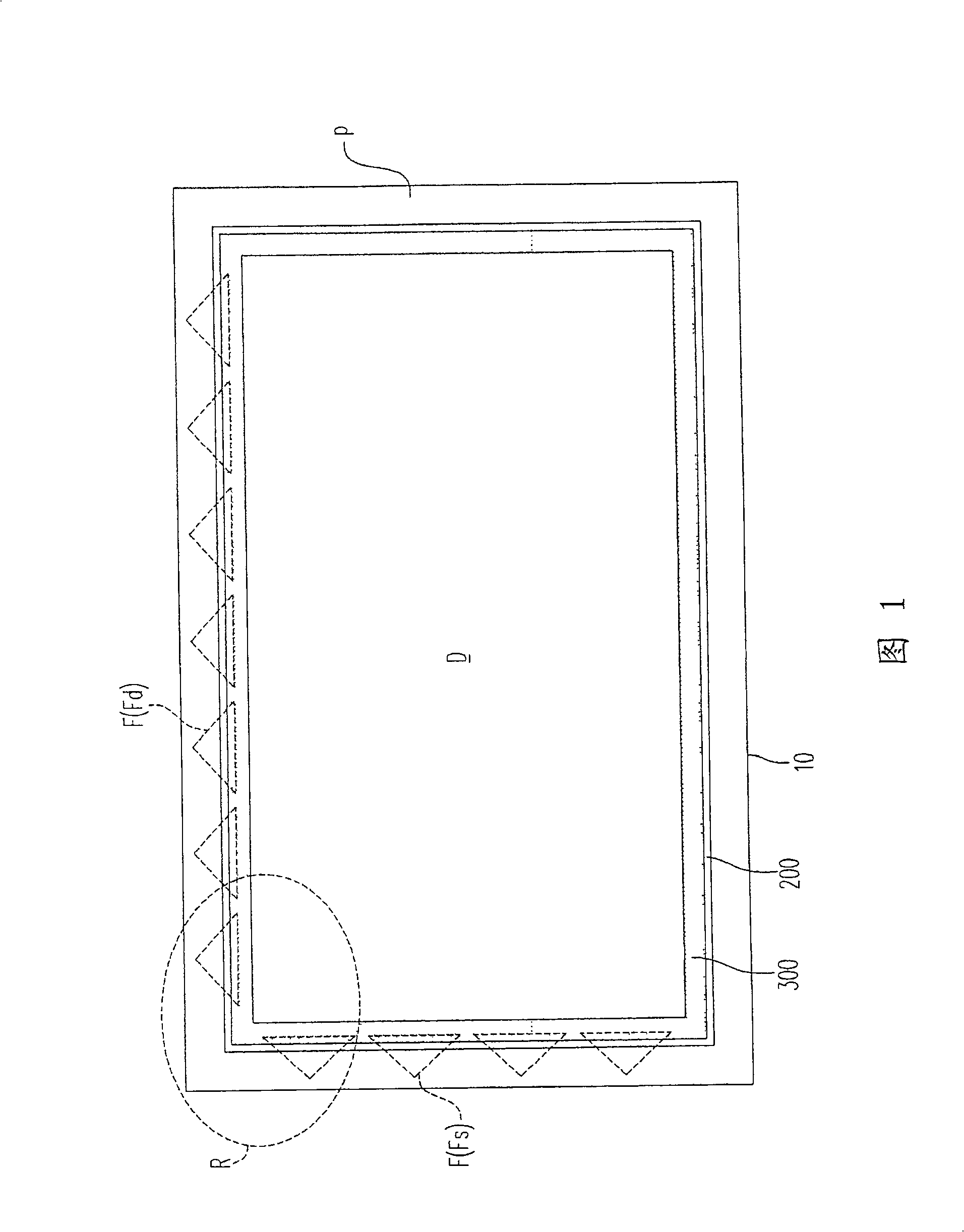
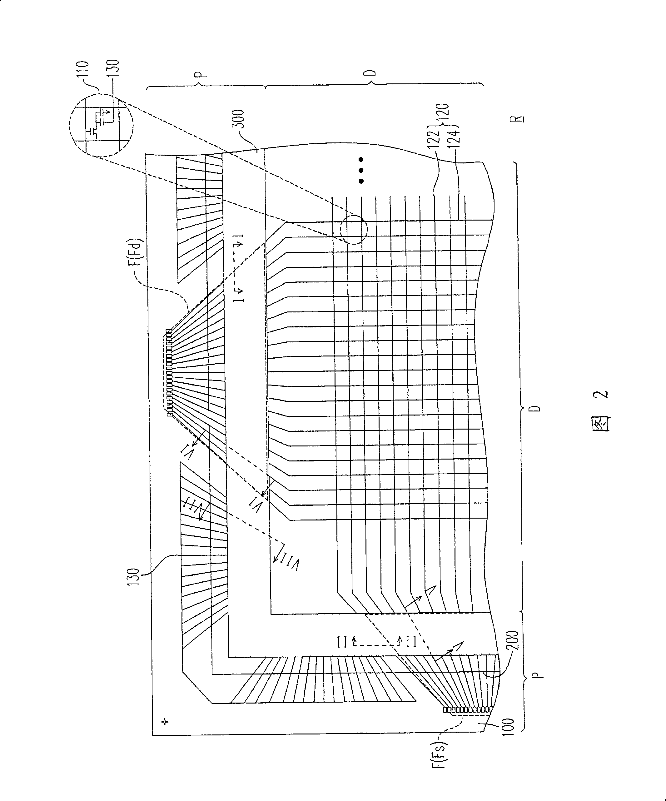
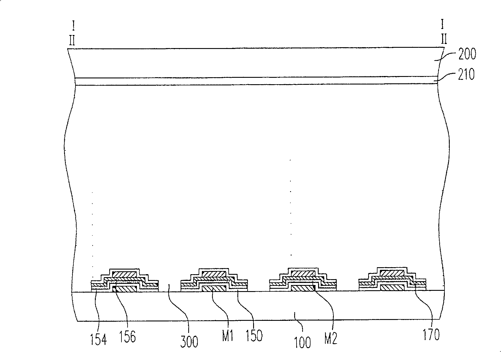
[0044] FIG. 1 is a top view of a liquid crystal display panel according to an embodiment of the present invention; FIG. 2 is an enlarged view of the marked area R in FIG. 1; image 3 It is a sectional view along the section line I-I or II-II in Fig. 2; Figure 4 is an enlarged view of the pixel in Figure 2; Figure 5 is along the Figure 4 Sectional drawing of section line IV-IV; Image 6 is a sectional view along the section line V-V of Fig. 2; Figure 7 It is a sectional view along the section line VI-VI of Fig. 2; Figure 8 It is a sectional view taken along the section line VII-VII in FIG. 2 .

[0045]Please refer to FIGS. 1 , 2 , 4 and 5 at the same time. The liquid crystal display panel of the present invention includes a first substrate 100 , a second substrate 200 , a sealant 300 and a liquid crystal layer 400 . The first substrate 100 and the components disposed on the first substrate 100 constitute an active device array substrate 10, wherein these components inclu...


PUM


Abstract

The invention discloses liquid crystal display panel. It includes active device array base plate, the second base plate, frame glue, and liquid crystal layer. The active device array base plate has display area and its perimeter circuit area, includes the first base plate, pixel, signal line, floating line, and line sharing layer. The signal line and the pixel are electrical property connected. The floating line is set at the fan-out area of the perimeter circuit area each which is aimed at one signal line. The line sharing layer is set out of the fan-out area of which thickness is the same as the whole of the aligned floating line and the signal line. The frame glue is covered over the floating line, part of signal line and line sharing layer around the display area.

Description

technical field [0001] The present invention relates to a liquid crystal display panel, and more particularly to a liquid crystal display panel that prevents display unevenness (mura). Background technique [0002] Since the invention of the first black-and-white television using a cathode ray tube (cathode ray tube, CRT) as the working mode, display technology has been evolving at a rapid pace. However, due to the disadvantages of such a display working in the cathode ray tube mode, such as bulky, heavy, high radiation, and poor image quality, new flat panel display technologies are constantly being developed. Among these flat panel display technologies, the liquid crystal display (LCD) technology is the most mature and popularized with the advantages of thinness, lightness, power saving, no radiation, full color, and portability. For example, mobile phones, language translators, digital cameras, digital video cameras, personal digital assistants (PDAs), notebook computers...

Claims


Application Information

Patent Timeline
Patent Type & Authority Patents(China)
IPC IPC(8): G02F1/136G02F1/133
Inventor 蔡淑芬杜振宇万仁文
Owner AU OPTRONICS CORP
Why Eureka
Try Eureka