Fuel injection valve for internal combustion engines

一种燃料喷射阀、内燃机的技术,应用在燃料喷射装置、装料系统、机械设备等方向,能够解决最佳喷射不再得到保证等问题,达到可靠压力卸载的效果

Inactive Publication Date: 2008-09-03
ROBERT BOSCH GMBH
View PDF5 Cites 1 Cited by
  • Summary
  • Abstract
  • Description
  • Claims
  • Application Information

AI Technical Summary

Problems solved by technology

For precise fuel injection, such as it is necessary for high-speed rotating compression-ignition internal combustion engines, this variation in the opening dynamics in terms of pollutant emissions and fuel consumption means that optimum injection is no longer guaranteed

Method used


Image

  • Fuel injection valve for internal combustion engines
  • Fuel injection valve for internal combustion engines
  • Fuel injection valve for internal combustion engines

Examples


Embodiment Construction

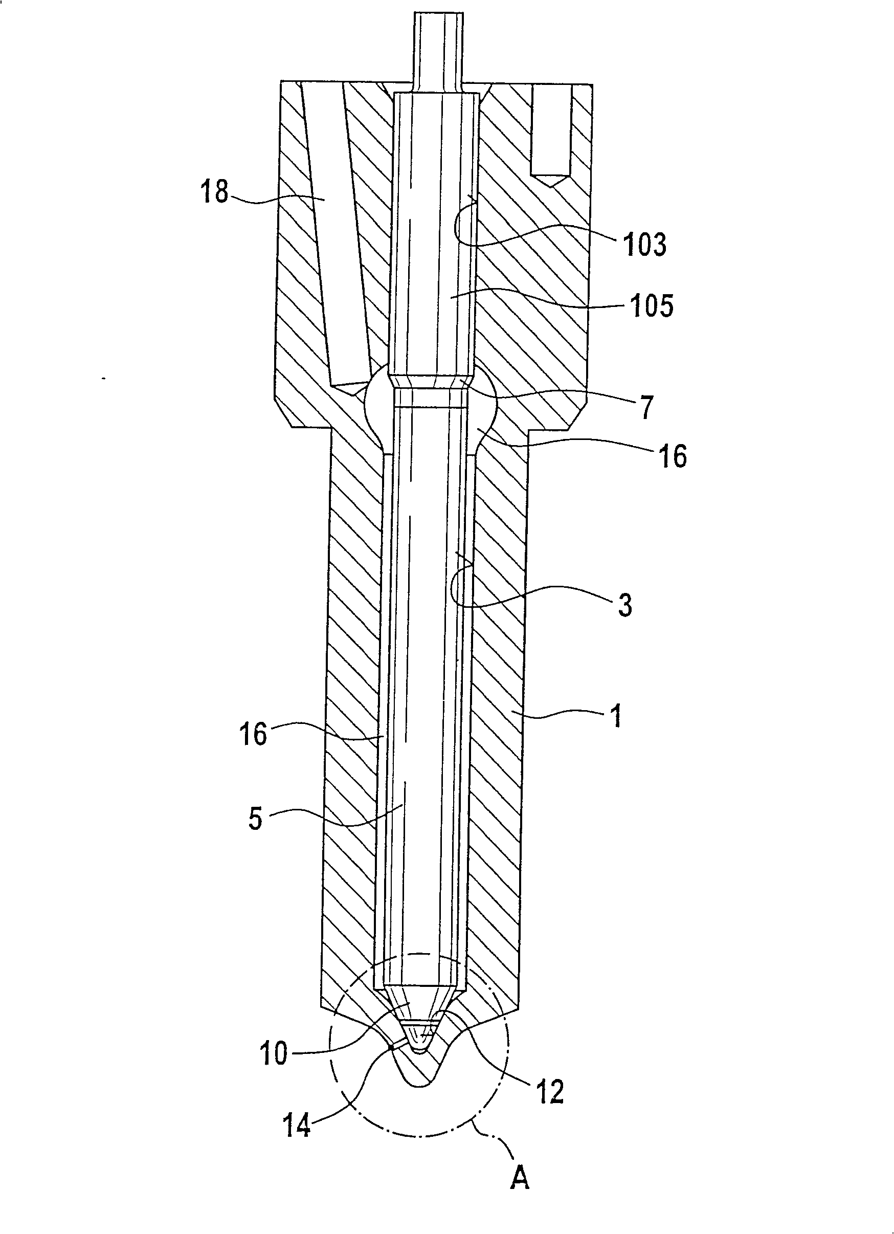
[0044] figure 1 A fuel injector according to the invention is shown in longitudinal section. A bore 3 is formed in the valve body 1 , which is delimited at its combustion chamber-side end by a conical valve seat 12 . At least one injection opening 14 leads from the valve seat 12 , which opens into the combustion chamber of the internal combustion engine in the installed position of the fuel injection valve. A piston-like valve needle 5 is arranged longitudinally displaceably in the bore 3 , which valve needle is guided by a guided section 105 in the guide section 103 of the bore 3 . Starting from the guided section 105 of the valve needle 5 , the valve needle 5 shrinks toward the valve seat 12 forming the pressure shoulder 7 and transitions into a valve sealing surface 10 at its combustion chamber-side end. In its closed position, the valve needle 5 bears against the valve seat 12 with the valve sealing surface 10, so that the nozzle opening 14 is closed with respect to the ...


PUM


Abstract

The invention relates to a fuel injection valve for internal combustion engines with a valve body (1), in which a drilling (3) is embodied, defined at the combustion chamber end thereof by a conical valve seat (12). A piston-like valve needle (5) is arranged in the drilling (3), such as to be longitudinally displaced, which comprises a valve sealing surface (10) at the combustion chamber end thereof which has two conical surfaces (20; 22). The second conical surface (22) is arranged on the combustion chamber side of the first conical surface (20) and an annular groove (25) runs between the conical surfaces (20; 22) the edge thereof facing away from the combustion chamber acting as a sealing edge (27) on location of the valve sealing surface (10) on the valve seat (12). Recesses are embodied on the valve seat (12) and / or on the valve sealing surface (10), hydraulically connecting the annular groove (25) with a section between the valve seat (12) and valve sealing surface (10) on the combustion chamber side of the annular groove (25).

Description

technical field [0001] The invention relates to a fuel injection valve for an internal combustion engine as known from the prior art. Background technique [0002] For example, the fuel injection valve known from WO 96 / 19661 has a valve body in which a bore is arranged, which bore is delimited at its end on the combustion chamber side by a conical valve seat. A piston-like valve needle is arranged longitudinally displaceable in this bore, which valve needle has an essentially conical valve sealing surface at its combustion chamber-side end. Here, the valve sealing surface is divided into two conical surfaces, which are separated from one another by an annular groove. The opening angles of these two conical surfaces are coordinated with the opening angles of the conical valve seat in such a way that when the valve needle rests on the valve seat, the edge formed at the transition from the annular groove to the first conical surface On the valve seat and used as a sealing edg...

Claims


Application Information

Patent Timeline
Patent Type & Authority Patents(China)
IPC IPC(8): F02M61/18
CPCF02M61/1866F02M61/18F02M61/1873
Inventor 马库斯·奥恩马克特帕特里克·马特斯维尔纳·特施纳威廉·克里斯特弗里德里希·伯金
Owner ROBERT BOSCH GMBH
Why Eureka
Try Eureka