Pressure detecting apparatus
A detection device and pressure technology, applied in measuring devices, fluid pressure measurement by changing ohmic resistance, rapid changes in measurement, etc., can solve problems such as cracks, disconnection, and bending
- Summary
- Abstract
- Description
- Claims
- Application Information
AI Technical Summary
Problems solved by technology
Method used
Image
Examples
no. 1 example
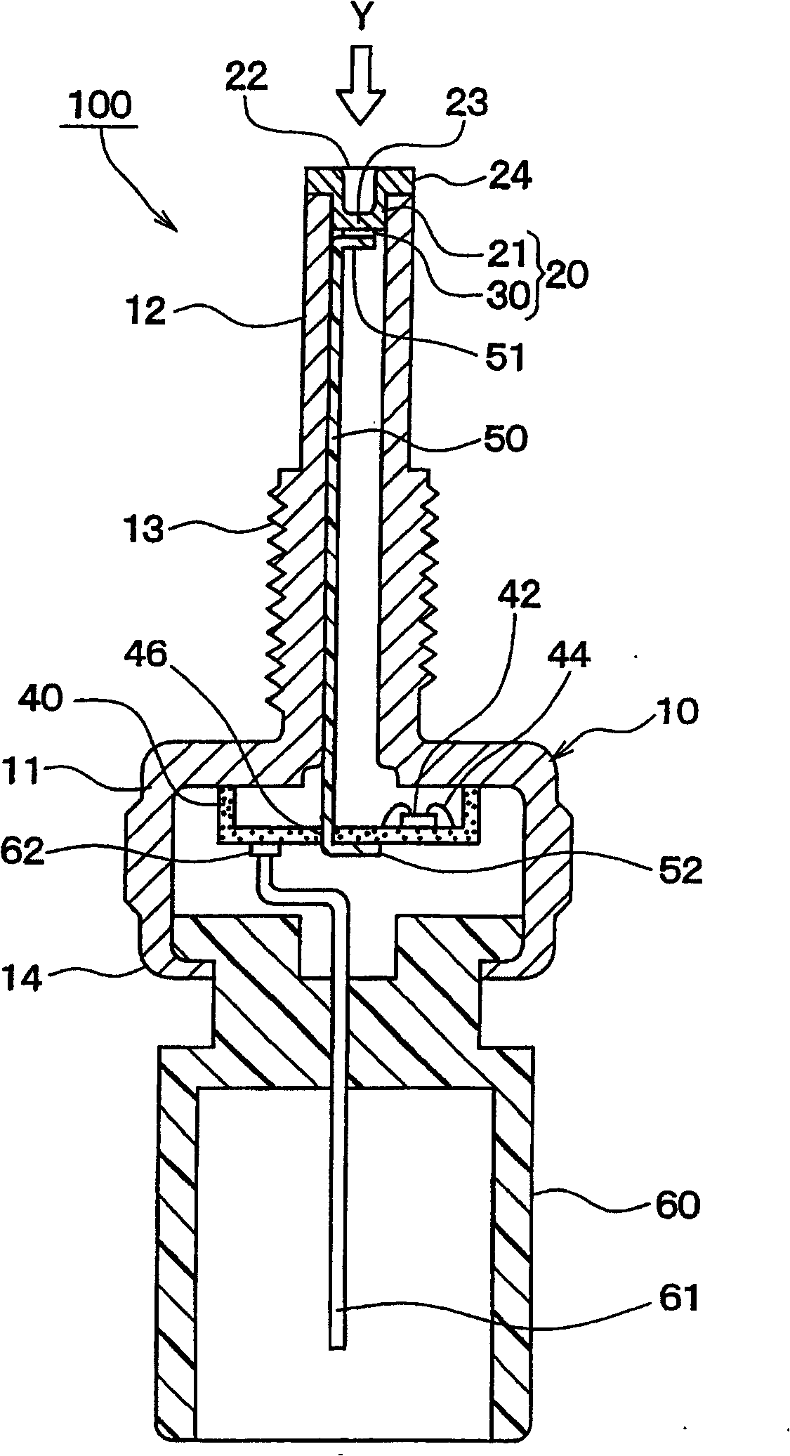
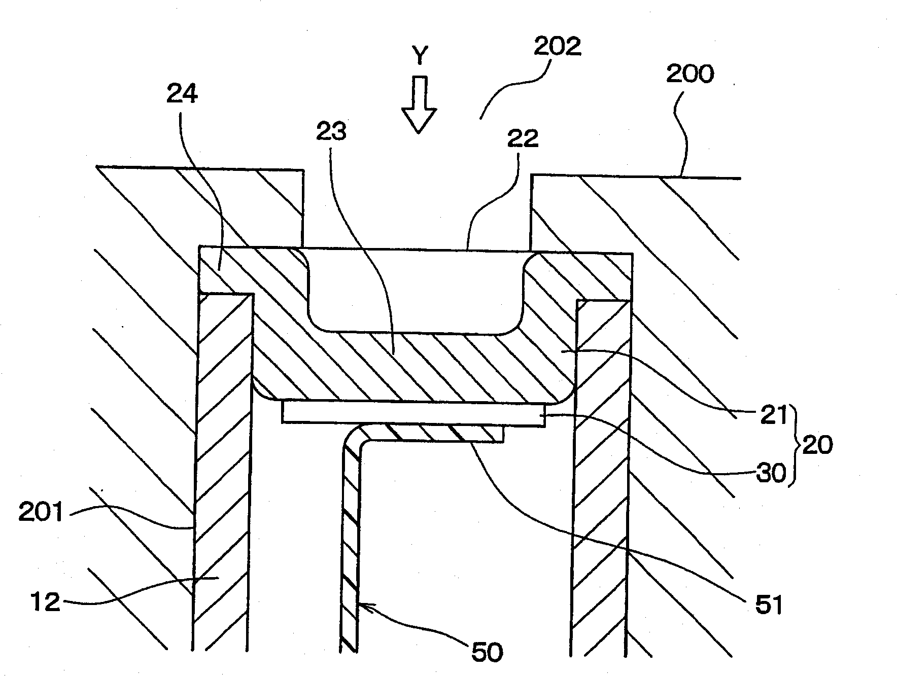
[0051] figure 1 It is a sectional view roughly showing the overall structure of the pressure detection device 100 according to the first embodiment of the present invention. in addition, figure 2 for showing figure 1 An enlarged view of a part of the pressure detection device 100 , wherein the part is the top of the pressure detection device 100 . It should be noted that in figure 2 In , engine block 200 is also shown.
[0052] Although the use of the pressure detection device 100 is not limited, the pressure detection device 100 can be applied as a combustion pressure sensor, while the pipe portion 12 of the casing 10 is installed in the installation hole 201, wherein the installation hole 201 is for example by means of The threaded connection is formed on the engine block 200 of the automobile as the object to be detected (see figure 2 ). The combustion pressure sensor (ie, inner cylinder pressure) detects the pressure inside the combustion chamber 202 as a detectio...
no. 2 example
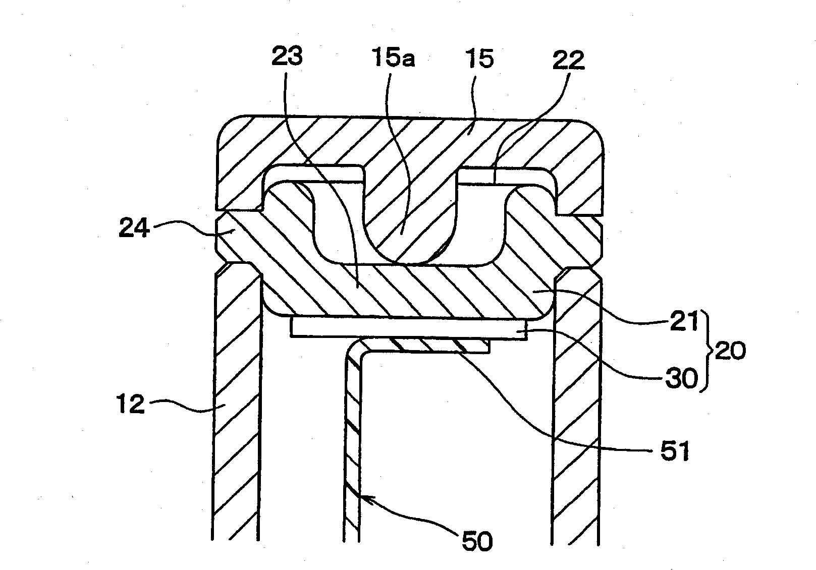
[0099] image 3 is a cross-sectional view roughly showing a main part of a pressure detecting device according to a second embodiment of the present invention. The difference between the pressure detection device and the first embodiment will be mainly described below.
[0100] In the above-mentioned first embodiment, when the pressure sensing element 20 is arranged such that the pressure sensing element 20 is exposed to the detection pressure environment, the detection pressure is directly applied to the pressure sensing element 20 .
[0101] Contrary to the first embodiment, in the pressure detection device of the second embodiment, such as image 3 As shown, the diaphragm 15 is arranged on the tip of the pipe part 12 in the housing 10 in such a way that it covers the pressure sensor element 20 . In this way, the probe pressure can be applied to the pressure sensor element 20 via the diaphragm 15 .
[0102] It can be understood that, hereinafter, the diaphragm 15 will be ...
no. 3 example
[0111] Figure 5is a cross-sectional view roughly showing a main part of a pressure detecting device according to a third embodiment of the present invention. The difference between the pressure detection device and the above-mentioned embodiment will be mainly described below.
[0112] Such as Figure 5 As shown, also in the third embodiment, the pressure-receiving-purpose diaphragm 15 is arranged at the tip of the pipe part 12 in such a way that the pressure-receiving-purpose diaphragm 15 covers the pressure sensing element 20, thereby The probe pressure can be applied to the pressure sensor element 20 via the pressure-receiving-purpose diaphragm 15 .
[0113] In the pressure detecting device according to the above-mentioned second embodiment, when the raised portion 15a is provided on the pressure-receiving-purpose diaphragm 15, the pressure-receiving-purpose diaphragm 15 is in direct contact with the pressure sensing element 20, The pressure detection device can thus be...
PUM
 Abstract
Description
Claims
Application Information
 - R&D
- Intellectual Property
- Life Sciences
- Materials
- Tech Scout
- Unparalleled Data Quality
- Higher Quality Content
- 60% Fewer Hallucinations
Browse by: Latest US Patents, China's latest patents, Technical Efficacy Thesaurus, Application Domain, Technology Topic, Popular Technical Reports.
© 2025 PatSnap. All rights reserved.Legal|Privacy policy|Modern Slavery Act Transparency Statement|Sitemap|About US| Contact US: help@patsnap.com


