
Method for grouping data channel adopted by indicating terminal transmitting data

A packet data channel and terminal transmission technology, applied in wireless communication, electrical components, radio/inductive link selection and arrangement, etc., can solve problems such as indication, low utilization rate of USF, occupation, etc.

Active Publication Date: 2009-01-07
HUAWEI TECH CO LTD
View PDF6 Cites 0 Cited by
  • Summary
  • Abstract
  • Description
  • Claims
  • Application Information

AI Technical Summary

Problems solved by technology

[0010] from image 3 It can be seen that the allocation of each uplink PDCH is determined by whether there is a USF corresponding to the terminal in the downlink PDCH corresponding to the uplink PDCH. Therefore, this allocation method has the disadvantage of high power consumption of the terminal: one terminal is allocated multiple When uplinking PDCH, the terminal must monitor the same number of downlink PDCHs as the number of allocated uplink PDCHs, so as to receive the allocated USF transmission data corresponding to the terminal, which will cause a large power consumption of the terminal
[0014] However, the extended dynamic allocation method has the disadvantage of low resource utilization in the communication system: Suppose there are two terminals whose uplink PDCH allocation methods are as follows: Figure 5 As shown, at this time, the amount of data to be sent by terminal 1 is relatively small, and only one uplink PDCH can be sent, and then the network side of the communication system will allocate terminal 1 to send uplink PDCH in time slot 3 (this is determined by the extension Determined by the dynamic allocation method, the uplink PDCH with the highest time slot is preferentially used for transmission), at this time, the amount of data to be sent by terminal 2 is large, but since the uplink PDCH of time slot 3 is already occupied by terminal 1, terminal 2 can only use the time slot 4 uplink PDCH, which will cause waste of uplink PDCH resources in time slot 0, time slot 1 and time slot 2, and make the resource utilization rate of the communication system not high
[0019] However, B2DA also has disadvantages: in order to be able to send all USFs corresponding to the uplink PDCH allocated to the terminal on the downlink PDCH corresponding to the uplink PDCH in the lowest time slot assigned to the terminal, currently the terminal is In the downlink PDCH corresponding to the uplink PDCH with the lowest assigned slot number, a terminal needs to occupy the same number of USFs as the allocated uplink PDCH, and only 8 USFs can be set in a downlink PDCH, which will cause terminal The downlink PDCH corresponding to the uplink PDCH of the slot with the lowest assigned slot number has a low multiplexing rate and a low USF utilization rate
For example: the network side of the communication system allocates the uplink PDCH of time slot 0, time slot 1, time slot 2, time slot 3 and time slot 4 and time slot 0, time slot 2, time slot 3, For the uplink PDCHs of time slot 4 and time slot 5, it is impossible to identify all the USFs of the uplink PDCHs allocated to terminal 1 and terminal 2 respectively in the downlink PDCH corresponding to the uplink PDCH of time slot 0 (terminal 1 and terminal 2 A total of 10 uplink PDCHs are allocated, and the downlink PDCH corresponding to the uplink PDCH of slot 0, that is, there can only be 8 USFs in the downlink PDCH of slot 0, which cannot be one-to-one correspondence), therefore, the time allocated for the terminal The downlink PDCH corresponding to the uplink PDCH with the lowest slot number has a low multiplexing rate and low USF utilization rate, so that the downlink PDCH corresponding to the uplink PDCH with the lowest slot number allocated to the terminal cannot be fully indicated by the USF as multiple Uplink PDCH allocated by terminals
Correspondingly, if USF is set according to this method, the multiplexing rate of the downlink PDCH corresponding to the uplink PDCH in other time slots allocated to the terminal is low and the utilization rate of the USF is low

Method used


Image

  • Method for grouping data channel adopted by indicating terminal transmitting data
  • Method for grouping data channel adopted by indicating terminal transmitting data
  • Method for grouping data channel adopted by indicating terminal transmitting data

Examples


Embodiment Construction

[0057] In order to make the object, technical solution and advantages of the present invention clearer, the present invention will be further described in detail by giving specific embodiments and referring to the accompanying drawings.

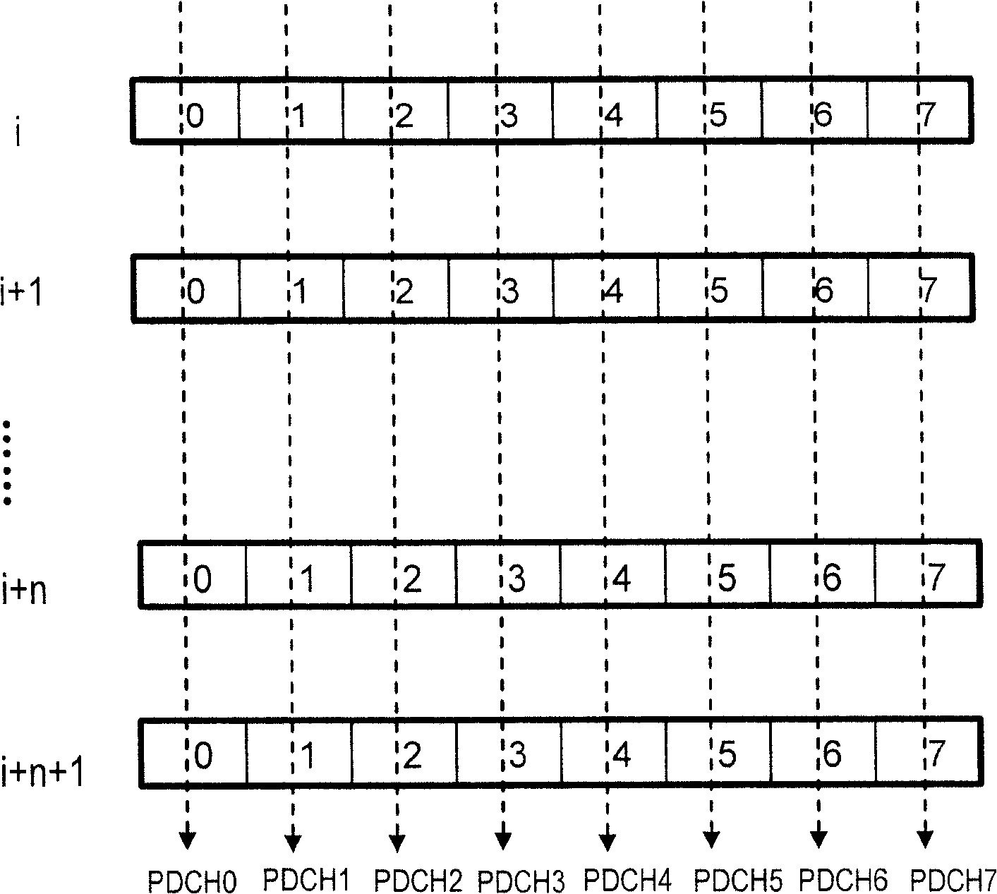
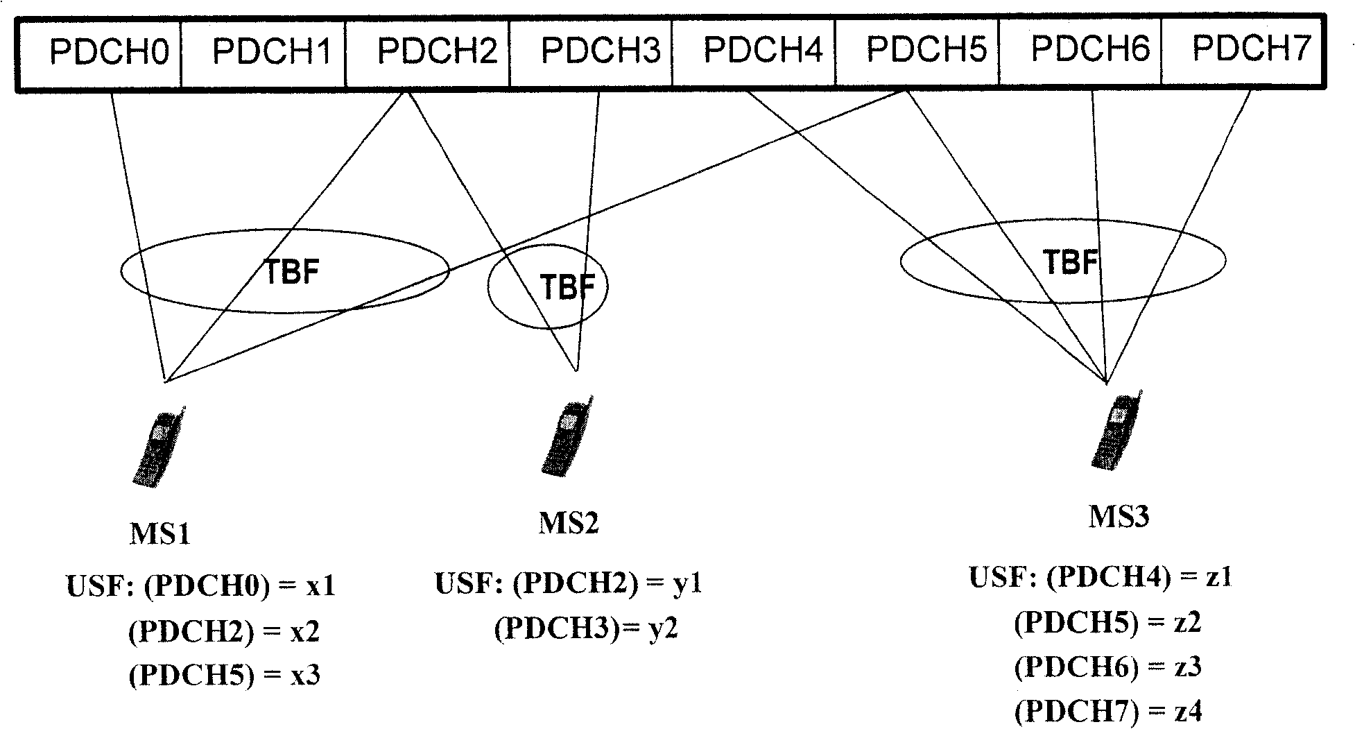
[0058] According to the method provided by the present invention, after the network side of the communication system allocates multiple uplink PDCHs for the terminal, if multiple USFs are set for the terminal on the downlink PDCH corresponding to one of the uplink PDCHs, the currently available USF resources for the downlink PDCH cannot be reached and allocated for the terminal. One-to-one correspondence between multiple uplink PDCHs, that is, when the number of USFs currently available for the downlink PDCH is less than the number of uplink PDCHs allocated for the terminal, different or the same USFs can be set for the terminal to correspond to several uplink PDCHs in the uplink PDCHs allocated for the terminal. That is, jumping indicates the...


PUM


Abstract

The method thereof comprises: a) in downlink PDCH corresponding to one of uplink PDCHs allocated for the terminal, after allocating downlink PDCH corresponding to the one of uplink PDCHs by USFs whose amounts are less than the amounts of PDCHs at network side of communication system, the network side of communication network informs the terminal to monitor the downlink PDCH; b) after the downlink PDCH monitors USFs, according to relevant mode, the downlink PDCH determines the uplink PDCH corresponding to the USF; send data through all uplink PDCHs whose time slot number allocated for terminal is not higher than the time slot of its corresponding uplink time slot.

Description

technical field [0001] The present invention relates to the technique of allocating packet data channel (PDCH) in the communication system, in particular to a method of indicating the PDCH used by the terminal to send data. Background technique [0002] At present, when a terminal in a communication system, such as a terminal in a General Packet Radio Service (GPRS) system or a Global System for Mobile Communications (GSM), wants to send data to the communication system network side, it first sends a data-carrying service to the communication system network side. Assignment of characteristic parameters Uplink channel request, the service characteristic parameters are the rate, delay and error rate of the data to be sent; secondly, the network side of the communication system allocates the uplink PDCH for the terminal according to the data service characteristic parameters received in the request Afterwards, the allocated uplink PDCH is indicated to the terminal; finally, the...

Claims


Application Information

Patent Timeline
Patent Type & Authority Patents(China)
IPC IPC(8): H04Q7/22H04Q7/38H04W72/04
Inventor 房明王之曦
Owner HUAWEI TECH CO LTD
Learn More