Zoom lens and digital camera and portable information apparatus

A zoom lens and lens technology, applied in the field of zoom lenses, can solve the problems of difficulty in correcting chromatic aberration, increase in the total length of the optical system, and inability to reduce the thickness of the lens, and achieve the effect of fully correcting chromatic aberration

Inactive Publication Date: 2009-02-04
SHARP KK
View PDF7 Cites 0 Cited by
  • Summary
  • Abstract
  • Description
  • Claims
  • Application Information

AI Technical Summary

Problems solved by technology

[0006] However, in the structure disclosed in JP H11-249016, the fourth lens group composed of two lenses is close to the image plane, so its outer diameter is very large and its radius of curvature is very small, which will make the thickness of the lens unable to be reduced
Therefore, the fourth lens group consisting of two lenses significantly increases the overall length of the optical system
Furthermore, as disclosed in JP 3493406, each lens group consisting of one lens makes it difficult to correct chromatic aberration

Method used


Image

  • Zoom lens and digital camera and portable information apparatus
  • Zoom lens and digital camera and portable information apparatus
  • Zoom lens and digital camera and portable information apparatus

Examples


no. 1 example

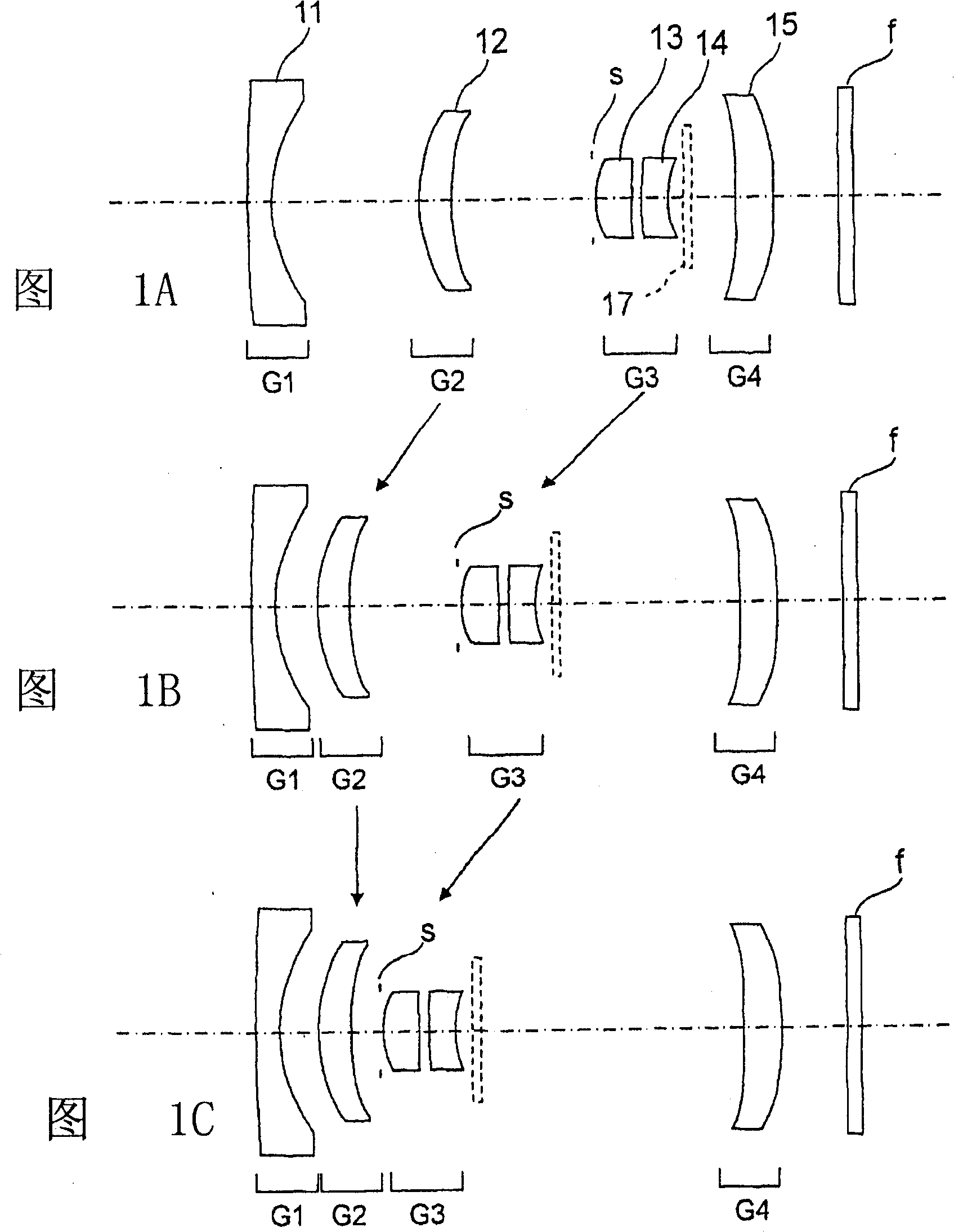
[0061] 1 is a cross-sectional view showing the structure of a zoom lens according to a first embodiment of the present invention, wherein FIG. 1A shows a zoom position at a wide-angle end in a cross section, and FIG. 1B shows a zoom position at an intermediate focal length in a cross section. zoom position, while Figure 1C shows the zoom position at the telephoto end in cross-section. In Figure 1, the left-hand side is the object space and the right-hand side is the image space. The arrows in the figure show the movement of each lens during zooming.

[0062] As shown in FIG. 1, the zoom lens in the first embodiment includes a first lens group G1 with a negative refractive index, a second lens group G2 with a positive refractive index, a third lens group G3 with a positive refractive index, and It is the positive fourth lens group G4, and the first lens group G1, the second lens group G2, the third lens group G3 and the fourth lens group G4 are arranged sequentially from the o...

no. 2 example

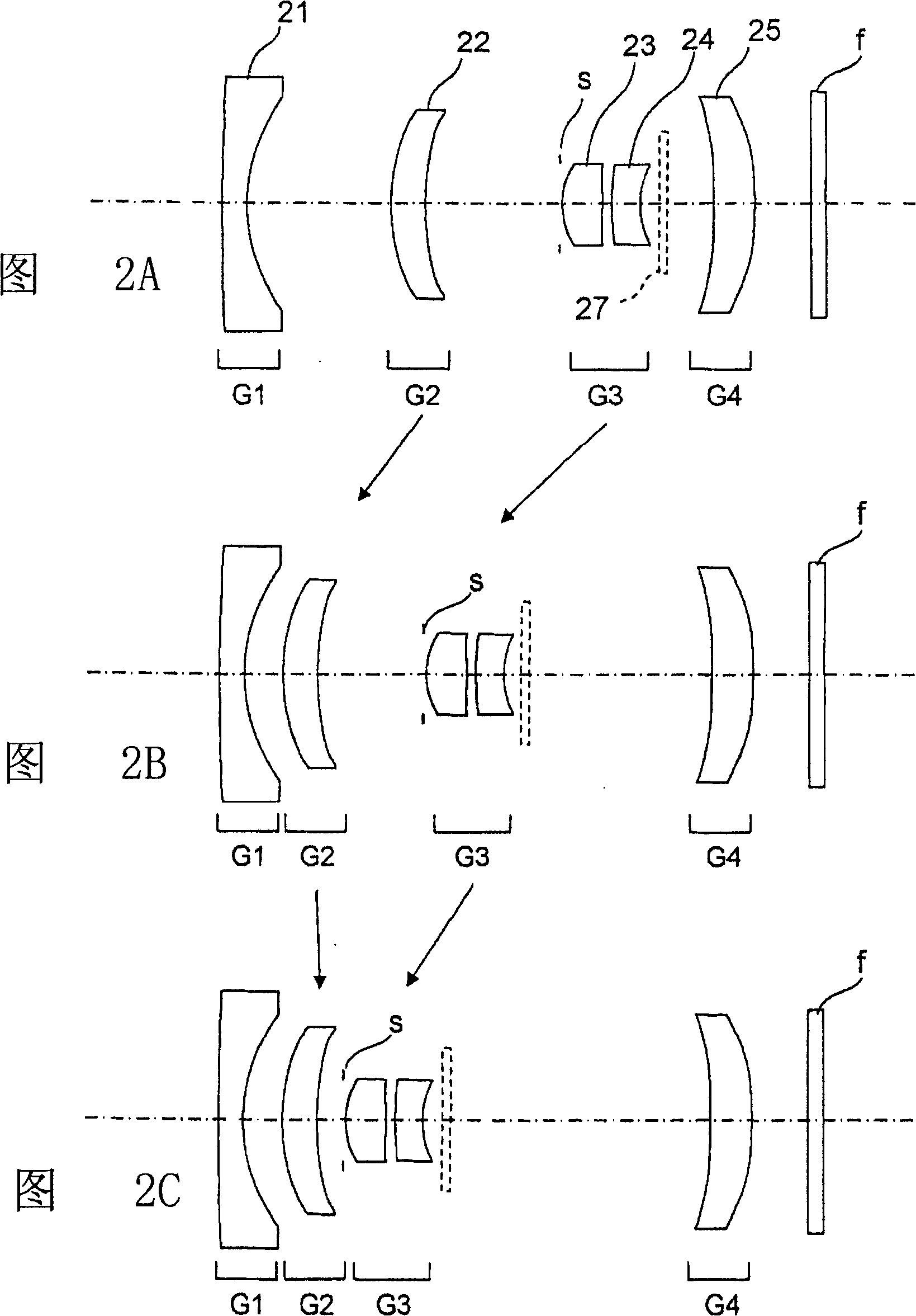
[0091] 2 is a cross-sectional view showing the structure of a zoom lens according to a second embodiment of the present invention, wherein FIG. 2A shows a zoom position at a wide-angle end in cross section, and FIG. 2B shows an intermediate focal length in cross section. The zoom position at , while FIG. 2C shows the zoom position at the telephoto end in cross-section. In Figure 2, the left-hand side is the object space and the right-hand side is the image space. The arrows in the figure show the movement of each lens during zooming.

[0092]As shown in FIG. 2, the zoom lens of the second embodiment includes a first lens group G1 with a negative refractive index, a second lens group G2 with a positive refractive index, a third lens group G3 with a positive refractive index, and a lens group with a positive refractive index. For the positive fourth lens group G4, the first lens group G1, the second lens group G2, the third lens group G3 and the fourth lens group G4 are arrange...

no. 3 example

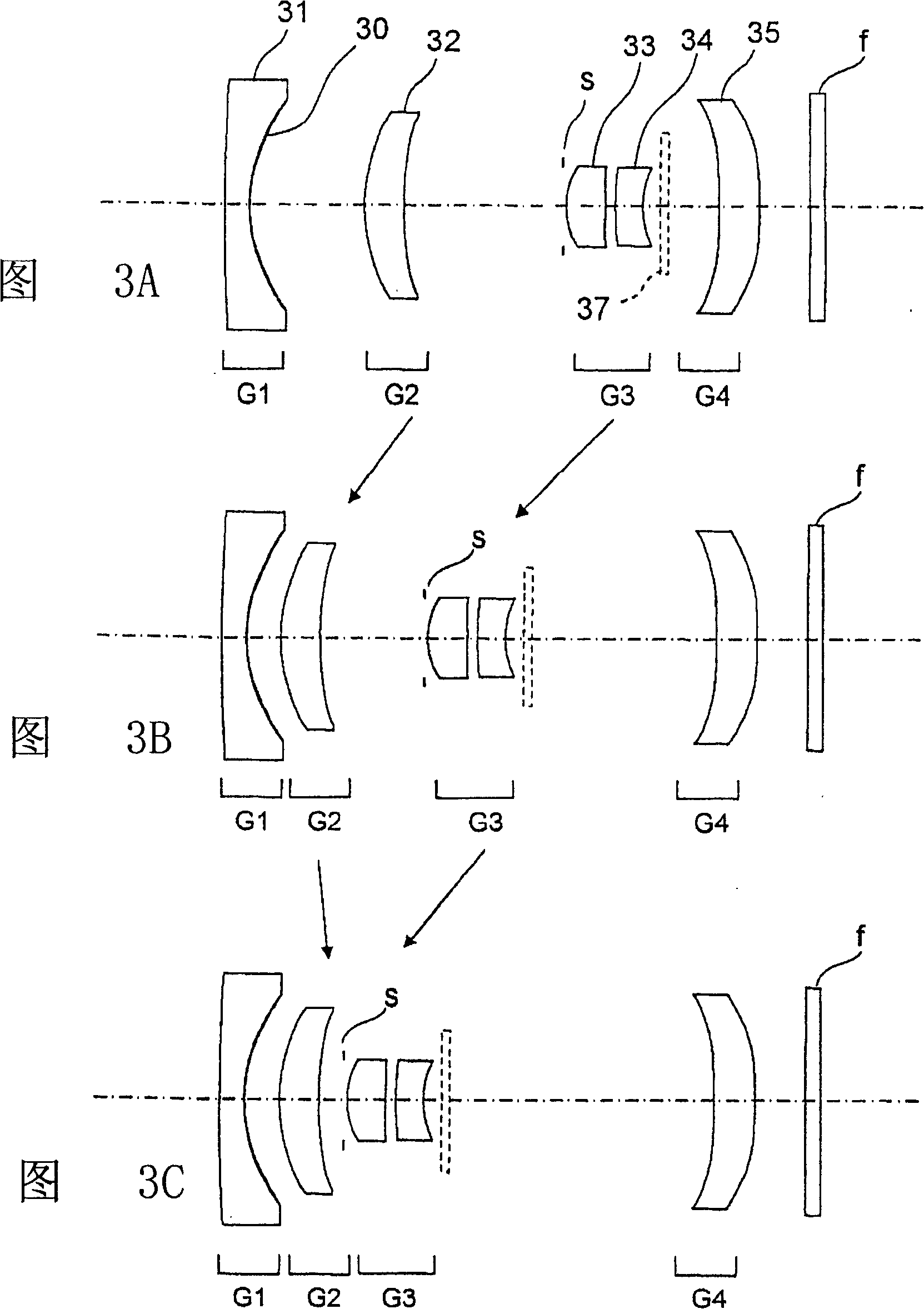
[0116] 3 is a cross-sectional view showing the structure of a zoom lens according to a third embodiment of the present invention, wherein FIG. 3A shows a zoom position at a wide-angle end in cross section, and FIG. 3B shows an intermediate focal length in cross section. The zoom position at , while FIG. 3C shows the zoom position at the telephoto end in cross-section. In Figure 3, the left-hand side is the object space and the right-hand side is the image space. The arrows in the figure show the movement of each lens during zooming.

[0117] As shown in FIG. 3, the zoom lens of the third embodiment includes a first lens group G1 with a negative refractive index, a second lens group G2 with a positive refractive index, a third lens group G3 with a positive refractive index, and a lens group with a positive refractive index. For the positive fourth lens group G4, the first lens group G1, the second lens group G2, the third lens group G3 and the fourth lens group G4 are arranged...


PUM


Abstract

A zoom lens in the present invention is composed of a first lens group G1 having a fixed distance from the image plane side and negative refracting power, a second lens group G2 having positive refracting power and moving during zooming, a third lens group G3 having positive refracting power and moving during zooming, and a fourth lens group G4 having a fixed distance from the image plane side and positive refracting power. The first, the second, the third and the fourth lens groups G1-G4 are arranged in order from the object side to the image plane side. The third lens group G3 includes an aperture stop s, a lens 13 having positive refracting power and a lens 14 having negative refracting power, being arranged in order from the object side to the image plane side. The zoom lens is high performance and large in zoom ratio and is compact due to the simple structure.

Description

technical field [0001] The present invention relates to a small-sized zoom lens, and particularly to a zoom lens that is included in a hand-held terminal and a mobile phone and has excellent portability due to a reduction in the overall length of the lens, and also to a digital camera and a portable lens using the zoom lens information equipment. Background technique [0002] In recent years, hand-held terminals such as PDAs (Personal Digital Assistants), mobile phones, etc. have spread, and most of them carry imaging devices such as digital cameras. These imaging devices use small-sized CCD (Charge Coupled Device) and CMOS (Complementary Metal Oxide Semiconductor) sensors to achieve miniaturization. As these devices spread, imaging devices are required to be smaller and to achieve high definition and high performance, with the result that zoom lenses are mounted on thin castings such as mobile phones. [0003] In such a zoom lens mounted on a portable terminal such as a m...

Claims


Application Information

Patent Timeline
Patent Type & Authority Patents(China)
IPC IPC(8): G02B15/14G02B9/34G02B13/18H04N5/225
Inventor 上田稔
Owner SHARP KK
Why Eureka
Try Eureka