Choke coil and its embedded iron core
A choke coil, iron core technology, applied in the direction of magnetic core/yoke, inductor with magnetic core, transformer/inductor magnetic core, etc., can solve the problem of large area of choke coil, disadvantage of miniaturization, and increase of material cost And other issues
- Summary
- Abstract
- Description
- Claims
- Application Information
AI Technical Summary
Problems solved by technology
Method used
Image

Examples
Embodiment Construction
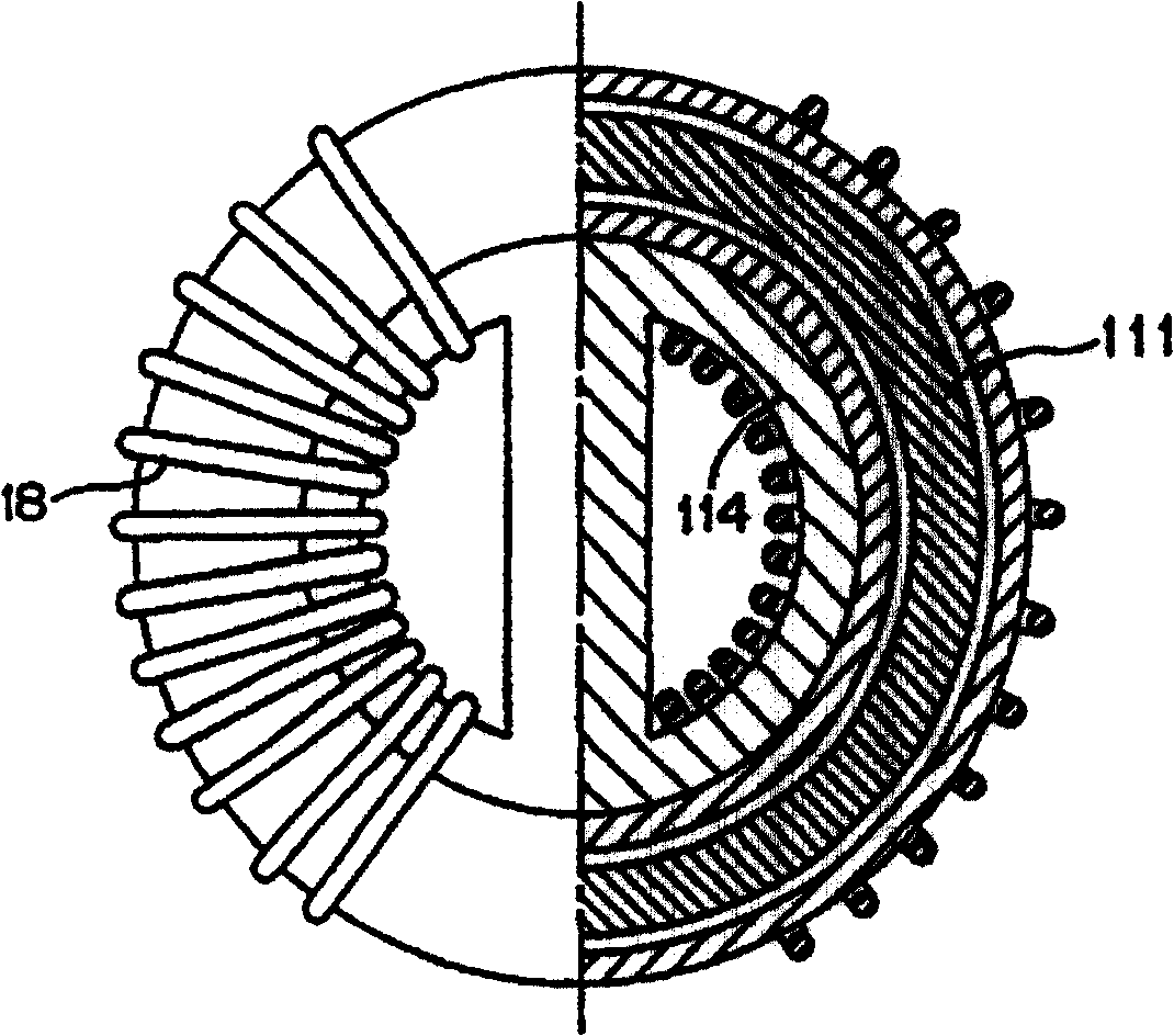
[0021] Please refer to Figure 2A , which is a schematic diagram of a choke coil according to a preferred embodiment of the present invention. The choke coil 20 disclosed in the preferred embodiment of the present invention includes an iron core 22 and two sets of winding wires 28. For clarity, an imaginary line L is used as the criterion. The right half of the figure only shows the inside of the iron core 22. And the left half of this figure is still a schematic diagram of the choke coil 20 .
[0022] Please also refer to Figure 2A , Figure 2B ,and Figure 2C , Figure 2B yes Figure 2A A schematic diagram of the interior of the core, while Figure 2C yes Figure 2B Sectional view of the middle iron core along the direction A-A'. The iron core 22 includes a first iron core 22a and a second iron core 22b. The second iron core 22b is embedded in the first iron core 22a, and the two sets of windings 28 are respectively wound around the outside of the first iron core 2...
PUM
 Abstract
Description
Claims
Application Information