Universal carrying device

A carrying device and a general-purpose technology, which is applied in packaging, transportation and packaging, and packaging of fragile items, etc., can solve problems such as excessive materials, inability to reduce packaging consumables, and insufficient effective range of coating

Inactive Publication Date: 2009-02-11
ASIA OPTICAL CO INC
View PDF7 Cites 0 Cited by
  • Summary
  • Abstract
  • Description
  • Claims
  • Application Information

AI Technical Summary

Problems solved by technology

[0006] 1. As shown in Figure 2 again, because the bottom shell part 2 and the top cover part 3 are made of plastic material, the top cover part 3 will be closed on the bottom due to warping and deformation during the molding process. When the shell part 2 is on, a gap is easily formed between the first top surface 201 and the second bottom surface 302. When the gap is too large, it is easy to cause the optical lens 1 to tilt, flip, or even fall out, and the surface of the optical lens 1 is easy to Defects such as scratches or insufficient coating effective range
[0007] Two, this optical lens 1 is mostly applicable to the camera lens of mobile phone, and the size of the optical lens 1 that each mobile phone is matched with is not exactly the same. The device cannot be universally used for the optical lens 1 within the predetermined size difference range, which will cause a waste of mold cost for manufacturing the carrying device
[0008] 3. The carrying device is formed by combining the bottom shell part 2 and the top cover part 3. The overall consumption of materials is more, the volume is larger, and the cost is higher
[0009] Four, the bearing device after coating, on the first bottom surface 202 of this bottom case part 2, top cover part 3, on the second top surface 301, a layer of metal film will be attached, so this bottom case part 2 and this top cover part 3 It cannot be recycled and reused, and it cannot reduce the cost of packaging consumables and is less in line with the needs of environmental protection

Method used


Image

  • Universal carrying device
  • Universal carrying device
  • Universal carrying device

Examples


Embodiment Construction

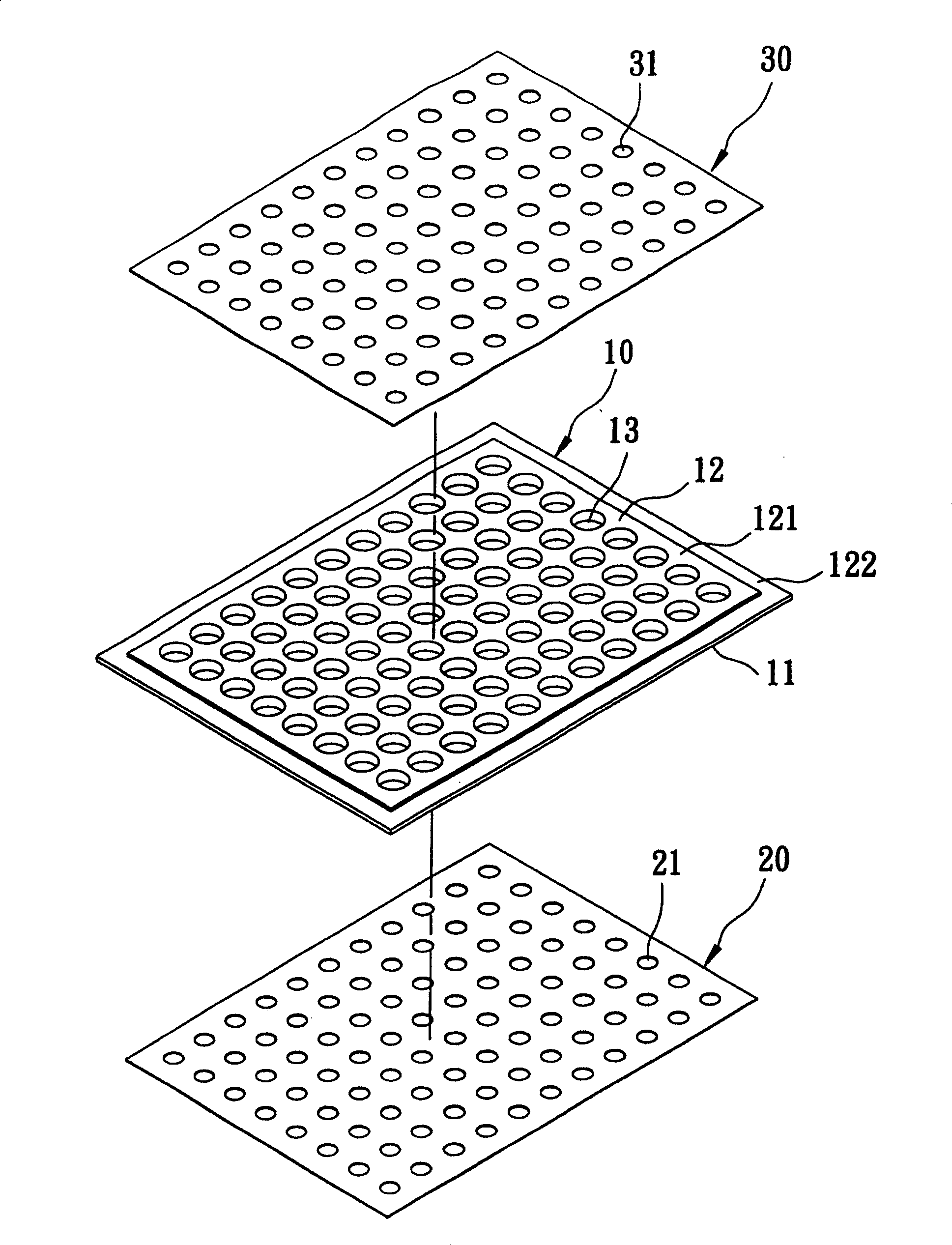
[0020] Such as image 3 As shown in Fig. 4, the preferred embodiment of the general-purpose carrying device of the present invention is suitable for accommodating a plurality of optical lenses 100, each of which has an outer diameter D1 and a light effective circle diameter smaller than the outer diameter D1 D2, and the carrying device includes a base body 10, a first positioning piece 20 detachably fixed on the base body 10, a set opposite to the first positioning piece 20 and is detachably fixed The second positioning piece 30 on the base body 10 .

[0021] The substrate 10 is made of polycarbonate material (PC) into a rectangular plate shape, and has a first surface 11, a second surface 12 opposite to the first surface 11, and a plurality of penetrating through the first and second surfaces. The receiving holes 13 on the surfaces 11 , 12 are defined to each have an inner diameter d1 greater than the outer diameter D1 of the optical lens 100 . The peripheral edges of the fi...


PUM


Abstract

The present invention discloses a universal type bearing device. It includes a base body, a first positioning sheet which can be removably fixed on a first surface of said base body and a second positioning sheet which is opposite to said first positioning sheet and is removably fixed on a second surface of said base body. Said base body has several bearing holes which are passed through said first surface and said second surface, and said first positioning sheet and second positioning sheet respectively have several first and second holes correspondent to these bearing holes, and the diameter of said first and second holes is less than inner diameter of said bearing holes, so that, after several optical lenses are placed in the bearing holes of said base body, the sealed arrangement of said first positioning sheet and second positioning sheet can be utilized to obtain spacing effect.

Description

technical field [0001] The invention relates to a lens holding device, in particular to a recyclable and reusable universal carrying device. Background technique [0002] Ordinary optical lens manufacturers will coat the optical lens after the optical lens is formed. After the coating is completed, the optical lens can be packaged and shipped to the manufacturer to be assembled. The processes of coating, packaging and shipping are all placed in a carrying device to avoid damage to the surface of the optical lens. [0003] As shown in Fig. 1, there is an existing carrying device for containing a plurality of optical lenses 1, which includes a bottom shell part 2 and a top cover part 3 covered on the bottom shell part 2, and the bottom shell part 2 has A first top surface 201, a first bottom surface 202 opposite to the first top surface 201, a plurality of first depressions 203 recessed from the first top surface 201, and a plurality of first depressions 203 formed by the fir...

Claims


Application Information

Patent Timeline
Patent Type & Authority Patents(China)
IPC IPC(8): B65D85/38B65D81/133B65D19/04
Inventor 蔡文雄
Owner ASIA OPTICAL CO INC
Why Eureka
Try Eureka