Control valve adjustor

A technology for valve adjustment and fluid control, applied to valve details, valve devices, engine components, etc., to achieve the effects of small leakage, increased service life, and small brake thrust requirements

Active Publication Date: 2009-02-11
FISHER CONTROLS INT LLC
View PDF6 Cites 0 Cited by
  • Summary
  • Abstract
  • Description
  • Claims
  • Application Information

AI Technical Summary

Problems solved by technology

[0003] Another disadvantage is that when these valves are used with conventional plug tips, they do not direct fluid away from the plug's seating surface to minimize unbalanced forces in the seating surface area

Method used


Image

  • Control valve adjustor
  • Control valve adjustor
  • Control valve adjustor

Examples


Embodiment Construction

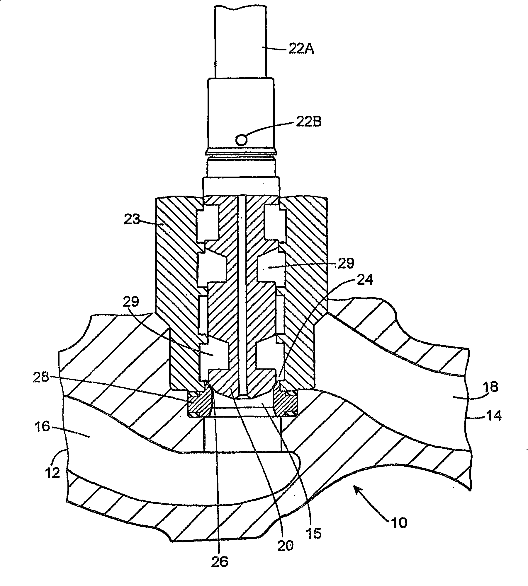
[0018] Figure 1 shows a conventional valve 10 with an anti-cavitation trim. Valve 10 includes a fluid inlet 12 , a fluid outlet 14 , and a fluid inlet passage 16 connecting fluid inlet 12 to a fluid outlet passage 18 through a bore 15 . Valve 10 is of the flow-up type in which fluid inlet 12 and fluid inlet passage 16 are located at a lower level than fluid outlet 14 and fluid outlet passage 18 . The valve plug 20 is connected by a valve stem 22A to an actuator, which is not shown but would be located on the valve stem 22A. One or more holes 22B are provided near the top of the valve plug 20 to receive, for example, grooved pins (not shown) to secure the connection of the valve plug 20 to the valve stem 22A. A cage 23 is located in the fluid flow path to affect desired fluid flow characteristics. An outer surface 24 of the valve plug 20 contacts a surface 26 of a seat ring 28 which forms a valve seat for the valve plug 20 .

[0019] In an effort to prevent cavitation within...


PUM


Abstract

The fluid control valve trim (31) and seat (28) with a plug (32) having a radius of approximately 0.03 inches, when used with a seat angle of approximately 75°, produces minimal unbalanced areas. The valve trim has pairs of anti-cavitation notches (42-52). The notches are arranged such that each particular pair of notches forms an angle with each other, and may further be arranged such that adjacent pairs of notches are offset relative to each other so as to increase the time the fluid is available for pressurization, as the fluid passes through the valve. , resulting in moderately graded and controlled pressure drops.

Description

technical field [0001] This invention relates generally to fluid control valves and, more particularly, to improvements in trim and seat design for fluid control valve plugs. Background technique [0002] Efforts have been made to design valve trims or sides with notches symmetrically disposed therein to define a preferred flow path for fluid within the valve. Typical of such efforts is Masoneilan / Dresser Industries' LINCOLNLOG TM Anti-cavitation adjustment for valve. The anti-cavitation trim stage pressure drops through the control valve. These valves suffer from a number of disadvantages. For example, in at least some cases, notches are located too close to each other to provide proper grading. As a result, fluid in the valve can flow from one choke to the next without the desired use of the interstage boost that is necessary to achieve the desired staging to avoid cavitation. This problem is referred to herein as a "short circuit". [0003] Another disadvantage is t...

Claims


Application Information

Patent Timeline
Patent Type & Authority Patents(China)
IPC IPC(8): F16K47/04
CPCF16K47/04Y10T137/86791
Inventor 内森·J·汉姆布林特德·A·龙
Owner FISHER CONTROLS INT LLC
Why Eureka
Try Eureka