
Eureka
For R&D, Eureka makes reading and utilizing patents & technical documents easy.
Eureka AIR
Designed for self-driven R&D workflows. Generate viable solutions, solve complex R&D challenges, empower your innovation with AI.

Eureka Materials
Designed for material experts only. Revolutionize your material R&D, from search, analyze, to developing new materials.

TechResearch
Generate reliable direction feasibility study reports for your R&D in just a few steps.

TechSeek
Discover and master advanced knowledge NOW. Basics, ideas, possibilities, all at once.

TechMind
As an expert in R&D Theories, TechMind can generates customized viable solutions instantly.

TechRisk
Analyze your overall solution with one click, know your potential R&D risks in advance.

TechMonitor
Get weekly tech updates, stay abreast of the latest tech innovations and key insights.
Projector with micro lens
A projector and micromirror technology, applied in the field of micromirror projectors, can solve the problems of strong graininess of the picture and insufficient fineness of the picture, and achieve the effect of fine picture and improved fineness
- Summary
- Abstract
- Description
- Claims
- Application Information
AI Technical Summary
Problems solved by technology
Method used
Image

Examples
Embodiment Construction
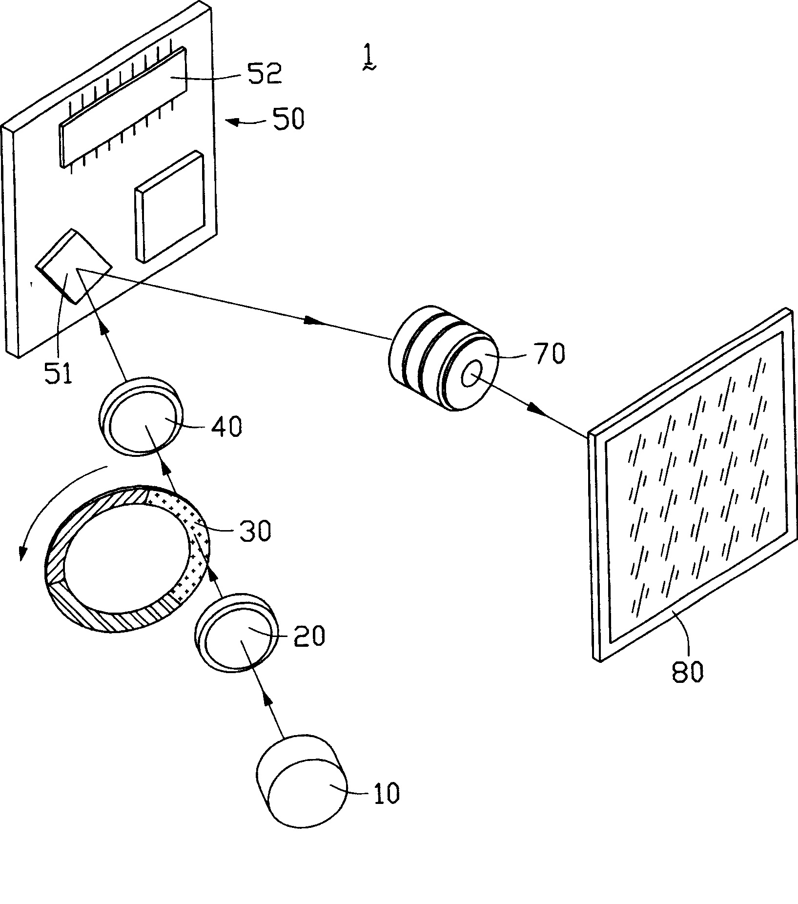
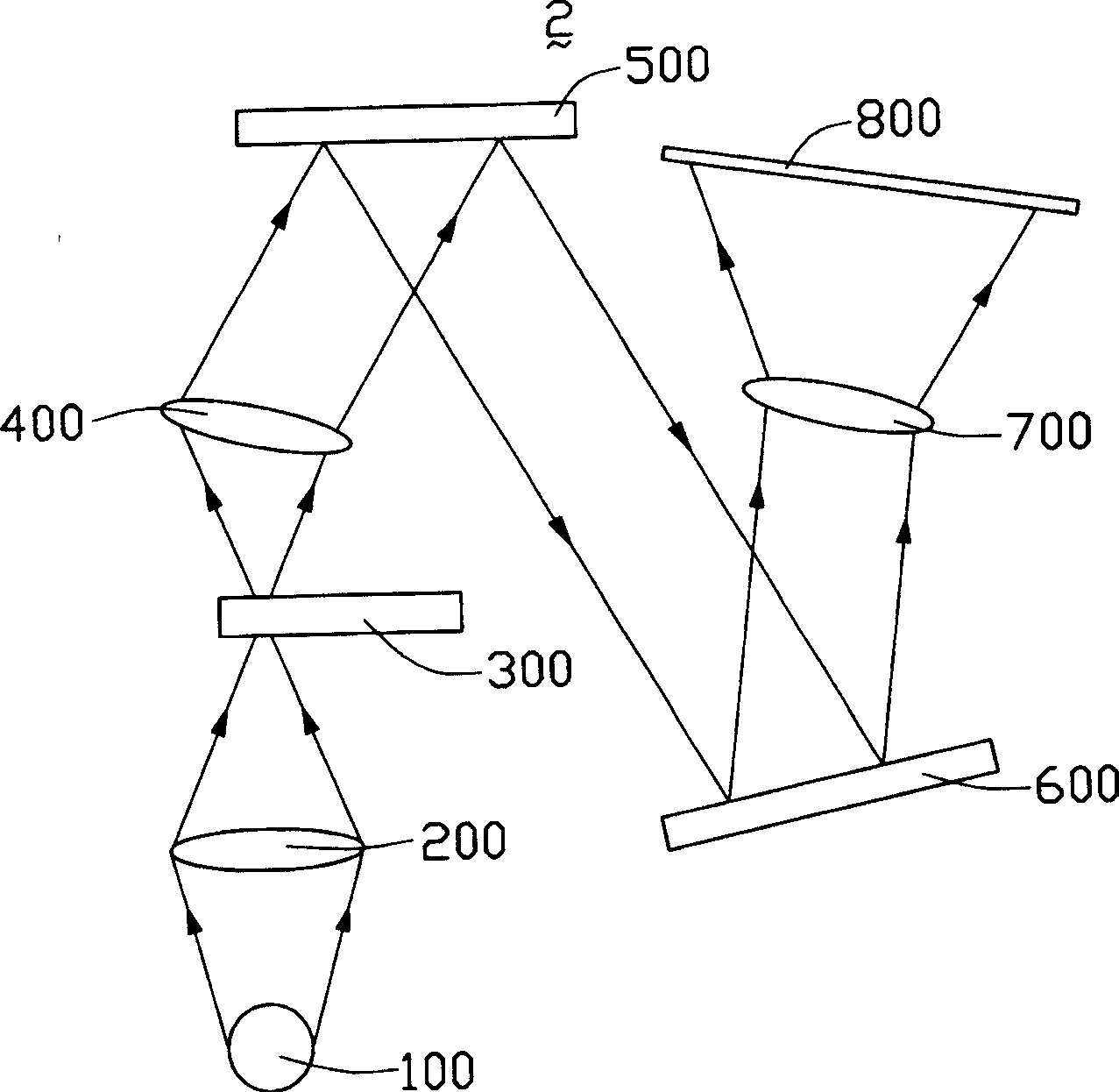
[0012] see figure 2 , is a schematic plan view of the micromirror projector of the present invention. The micromirror projector 2 of the present invention includes a light source 100 , a converging lens 200 , a color wheel 300 , a trimming lens 400 , a micromirror chip 500 , a diffraction component 600 and a projection component 700 . The color wheel 300 includes three color regions of red, green and blue, and can rotate at high speed. The micromirror chip 500 includes a micromirror component (not shown) with a plurality of micromirrors and a processor (not shown). The plurality of micromirrors receive signals from the processor to perform rapid switching actions.
[0013] The light emitted by the light source 100 is converged to the color wheel 300 through the converging lens 200, and the high-speed rotation of the color wheel makes the passing light turn into three monochromatic colors of red, green and blue in a very short time. The light is incident on the micromirror p...
PUM
 Abstract
Description
Claims
Application Information
 - R&D Engineer
- R&D Manager
- IP Professional
- Industry Leading Data Capabilities
- Powerful AI technology
- Patent DNA Extraction
Browse by: Latest US Patents, China's latest patents, Technical Efficacy Thesaurus, Application Domain, Technology Topic, Popular Technical Reports.
© 2024 PatSnap. All rights reserved.Legal|Privacy policy|Modern Slavery Act Transparency Statement|Sitemap|About US| Contact US: help@patsnap.com