
Four-quadrant multiplication circuit

A multiplication circuit and four-quadrant technology, applied in multiplication/division calculation operations, measurement of electrical variables, measurement devices, etc., can solve the problem of high circuit cost

Inactive Publication Date: 2009-02-25
VIMICRO CORP
View PDF2 Cites 0 Cited by
  • Summary
  • Abstract
  • Description
  • Claims
  • Application Information

AI Technical Summary

Problems solved by technology

[0009] However, to realize the above-mentioned four-quadrant multiplication circuit, two sets of filters are required, and the circuit cost is relatively high

Method used


Image

  • Four-quadrant multiplication circuit
  • Four-quadrant multiplication circuit
  • Four-quadrant multiplication circuit

Examples


Embodiment Construction

[0056] In order to make the object, technical solution and advantages of the present invention clearer, the present invention will be further described in detail below with reference to the accompanying drawings and examples.

[0057] The basic idea of ​​the present invention is: after the two-way time-varying digital signals extracted and filtered are modulated by the synchronous signal, after parallel / serial conversion into one-way input signal, the combined input signal is filtered through a high-pass filter, The DC offset in the attenuated signal is then passed through a serial multiplier to calculate the four-quadrant product of the two signals included in the input signal.

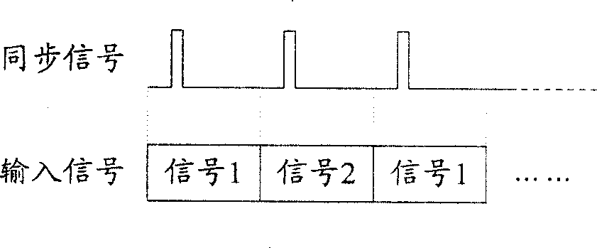
[0058] figure 2 It is a schematic diagram of the input signal of the four-quadrant multiplication circuit in the present invention. like figure 2 As shown, the input signal received by the four-quadrant multiplication circuit in the present invention is a signal obtained by two time-varying digit...


PUM


Abstract

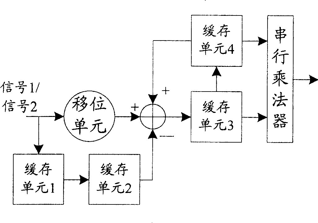
The invention discloses a four-quadrant multiplication circuits. The invention will take two roads digital signal from filtering, and with the modulation of synchronized signals, perform the parallel / serial conversion on the input to generate one road signals. The signals comes through a high-pass filter, which consists of a shift unit, first cache unit, second cache unit, third cache unit, fourth cache unit and calculator, to filter on the combined input signals, to attenuate DC bias in signals, and then to calculate the four-quadrant multiplication of the two roads signals contained in the input signals through a serial multiplier.

Description

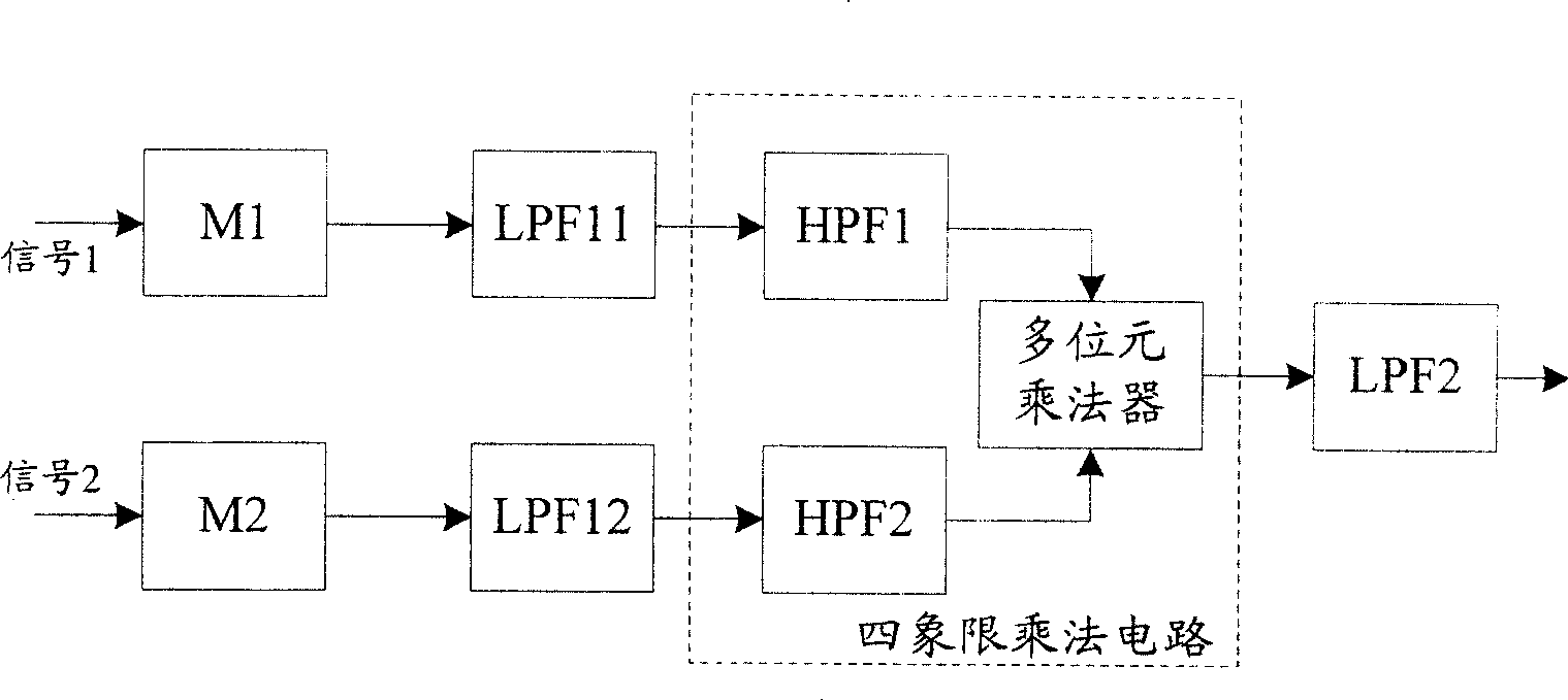
technical field [0001] The invention relates to digital circuit technology, in particular to a four-quadrant multiplication circuit. Background technique [0002] Four-quadrant multiplication refers to multiplying two time-varying signals to produce a real-time four-quadrant product. figure 1 It is a schematic diagram of a circuit structure for realizing four-quadrant multiplication in the prior art. like figure 1 As shown, the four-quadrant multiplication circuit usually includes: two high-pass filters (HPF1 and HPF2) and a multi-bit multiplier. [0003] Signal 1 and signal 2 are converted into two multi-bit digital signals after passing through two modulators (M1 and M2) and two first-stage low-pass filters (LPF11 and LPF12) respectively, and input to the four-quadrant multiplication circuit . M1 and M2, LPF11 and LPF12 mainly play the role of decimation filter. [0004] HPF1 and HPF2 in the four-quadrant multiplication circuit receive the multi-bit signal 1 and signa...

Claims


Application Information

Patent Timeline
Patent Type & Authority Patents(China)
IPC IPC(8): G06G7/16G01R11/00G01R19/02
Inventor 范志军
Owner VIMICRO CORP
Learn More