Supercharge Your Innovation With Domain-Expert AI Agents!

Method and device for controlling constant linear speed of mainshaft dynamo by using image signal

一种主轴电机、线速度的技术,应用在在磁盘上信息的记录、单个电动机转速/转矩控制、信息存储等方向,能够解决不精确、主轴电机不稳定等问题

Inactive Publication Date: 2009-04-01
SAMSUNG ELECTRONICS CO LTD
View PDF4 Cites 0 Cited by
  • Summary
  • Abstract
  • Description
  • Claims
  • Application Information

AI Technical Summary

Problems solved by technology

In this case, the rotation speed of the spindle motor is controlled based on the estimation, and accordingly, the operation of the spindle motor inevitably becomes unstable and imprecise

Method used


Image

  • Method and device for controlling constant linear speed of mainshaft dynamo by using image signal
  • Method and device for controlling constant linear speed of mainshaft dynamo by using image signal
  • Method and device for controlling constant linear speed of mainshaft dynamo by using image signal

Examples


Embodiment Construction

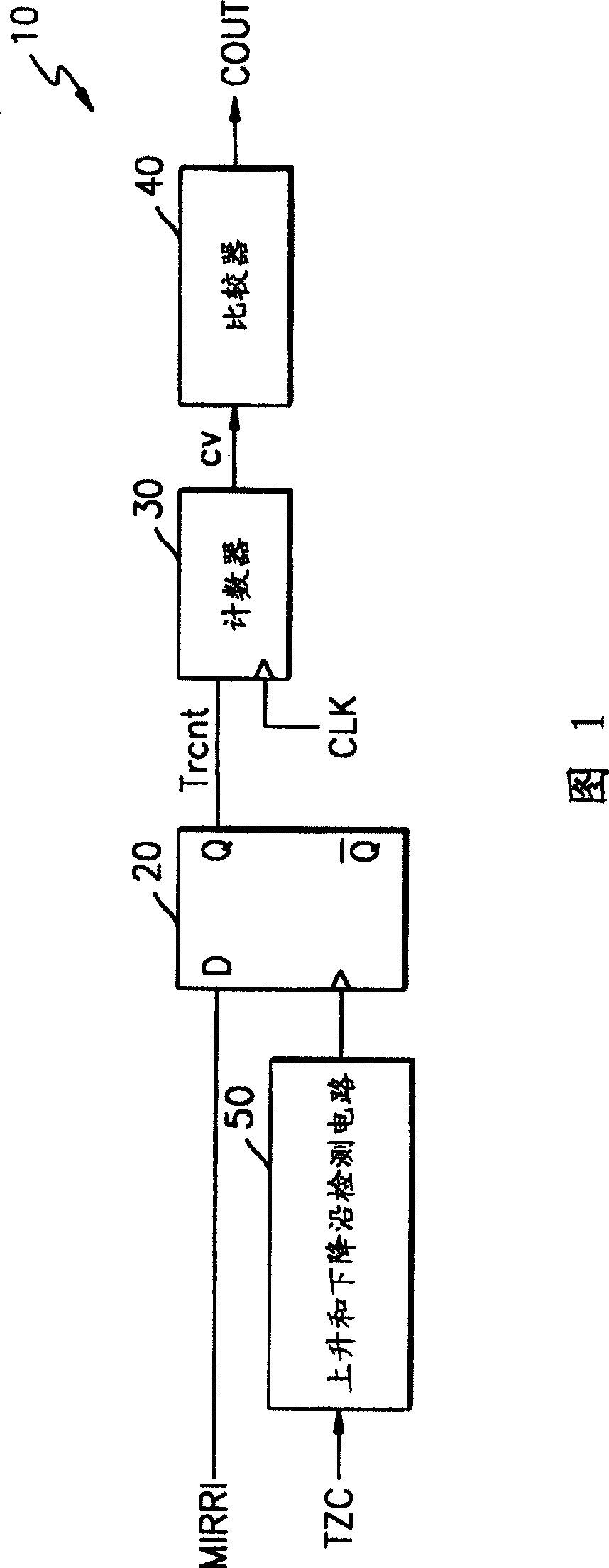
[0039] Fig. 1 shows a block diagram of an apparatus for controlling a constant linear velocity of a spindle motor according to a preferred embodiment of the present invention. Referring to FIG. 1, the device for controlling the constant linear velocity of a spindle motor (not shown) includes an image signal detection circuit 20, a counter 30, a comparator 40, and a rising and falling edge detection circuit 50, wherein the spindle motor is used to rotate such as CD, LD, or DVD discs.

[0040] The rising and falling edge detection circuit 50 receives a tracking zero-crossing signal TZC, detects the rising and falling voltages of the tracking zero-crossing signal TZC, and outputs the generated signal to the image signal detection circuit 20 as a detection result.

[0041] The mirror signal detection circuit 20 uses the signal output from the rising and falling edge detection circuit 50 for clock synchronization, the mirror signal detection circuit 20 detects the mirror signal MIR...


PUM

PropertyMeasurementUnit
frequencyaaaaaaaaaa

Abstract

A method and an apparatus for precisely controlling the rotation speed of a spindle motor in an optical system according to a given condition are provided. The method involves counting in response to a clock signal widths of first and second logic states of an input signal, which varies with rotation speed of the spindle motor, when an operation control command is issued, comparing a predetermined reference value with a count value for one check cycle, and outputting the comparison result; and controlling the constant linear velocity of the spindle motor in response to the comparison result.

Description

[0001] This application claims Korean Patent Application No. 2002-69419 filed with the Korean Intellectual Property Office on November 9, 2002, which is incorporated herein by reference in its entirety. technical field [0002] The present invention relates to a method and apparatus for controlling a constant linear velocity of a spindle motor used in an optical system, in particular to a method and a device for controlling a constant linear velocity of a spindle motor used in an optical system, and in particular to a method by combining the width of an image signal or an equivalent of an image signal in a first logic state with a second Method and apparatus for controlling a constant linear velocity of a spindle motor used in an optical system by comparing the widths of mirrored signals or equivalents of mirrored signals in two logic states. Background technique [0003] An optical system is a device for recording data thereon and / or reproducing data from an optical disc, su...

Claims


Application Information

Patent Timeline
Patent Type & Authority Patents(China)
IPC IPC(8): G11B19/20G11B19/28G11B20/10G11B19/22G11B19/247
CPCG11B19/28H02P6/08G11B19/247G11B19/20
Inventor 金济国张荣旭
Owner SAMSUNG ELECTRONICS CO LTD
Features
  • R&D
  • Intellectual Property
  • Life Sciences
  • Materials
  • Tech Scout
  • Unparalleled Data Quality
  • Higher Quality Content
  • 60% Fewer Hallucinations
Learn More