
CLV optical disc, CLV optical disc format, and an optical disc medium recording and reproducing apparatus

a technology of optical discs and discs, which is applied in the field of clv optical discs, clv optical disc formats, and optical disc medium recording and reproducing apparatuses, can solve the problems of difficult conversion between information numbers and tracks numbers, and no advantageous functional effect for improving clv optical discs and clv type methods of disc formatting,

Inactive Publication Date: 2005-09-06
RICOH KK
View PDF11 Cites 7 Cited by
  • Summary
  • Abstract
  • Description
  • Claims
  • Application Information

AI Technical Summary

Benefits of technology

The present invention provides an improved CLV optical disc and the CLV type method of disc formatting, which solves the problems of the background art. The invention enables faster and more efficient access to the disc information by calculating the logical information number and track number from each other, and accessing the disc information with high speed. The invention also addresses the issue of uneven format of the disc caused by the manufacturing process. The invention provides a solution for the CLV disc format to access the optional address with high speed. Additionally, the invention aims to provide the CLV optical disc medium recording / reproducing apparatus capable of performing the seeking operation independently from the operation of controlling the revolution rate of the disc. The invention also addresses the demand for high accuracy and quality in the optical disc cutting machine.

Problems solved by technology

However, according to such background arts which are disclosed in background-art documents, e.g., Japanese Laid-open Patent Publication Nos. 9-16980 and 8-279192, there exists no advantageous functional effect for improving the CLV optical disc and the CLV type method of disc formatting.
As the result, the conversion from the information number and the number of tracks, and vice versa, may become difficult.
Consequently, the conversion between the information number and the tracks number may become further difficult.

Method used


Image

  • CLV optical disc, CLV optical disc format, and an optical disc medium recording and reproducing apparatus
  • CLV optical disc, CLV optical disc format, and an optical disc medium recording and reproducing apparatus
  • CLV optical disc, CLV optical disc format, and an optical disc medium recording and reproducing apparatus

Examples


third embodiment

[0143]The third embodiment of the CLV optical disc according to the present invention is described concretely in detail hereinafter, referring to the accompanying drawings.

[0144]In a spiral track of equal pitch formed by the CLV driving, the railroad track length L of the entire track thereof is expressed by a below equation (1).

L=π×(r2−Ro2) / P  (1)

r=Ro+n×p(n=1, 2, 3, . . . )  (2)

Here, as shown in FIG. 4, the symbol Ro represents the radius position of starting the spiral, r represents the radius position of the spiral for intending to measure the railroad track length L, P represents the spiral track pitch, and n represents the number of the tracks.

[0145]An equation (3) shown below can be obtained from the above equations (1) and (2):

L=2×π×Ro×n+n2×π×P(n=1, 2, 3, . . . )  (3)

L=2×π×Ro+(2×n−1)×π×P(n=1, 2, 3, . . . )  (4)

[0146]From the equation (4), it is apparent that the railroad track length difference between the adjacent tracks is constant as shown below:

[Railroad Track Length Diff...

fourth embodiment

[0154]The fourth embodiment of the present invention is a structure of arranging track marks 53 at an equal physical interval on the land portions 52 along the groove portions 51 for recording or reproducing the information formed in the state of a spiral as shown in FIG. 9. As in the case of the third embodiment, the position of the present track mark can be calculated and specified from the distance between the track marks on the adjacent information track 55.

fifth embodiment

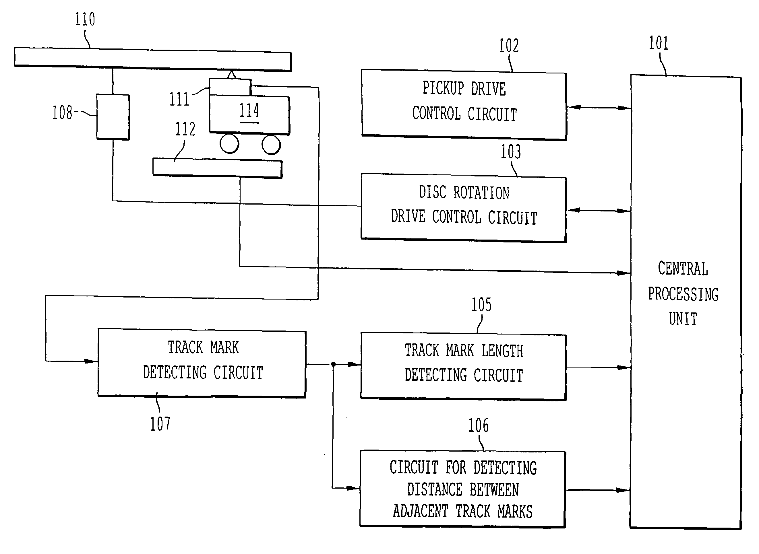
[0155]In comparison with the abovementioned CLV disc formats of the third and fourth embodiments, the fifth embodiment obtains the present track information from the information of the rough track position and track mark length and the distance information between the adjacent track marks, and thereby realizes a high-speed seeking operation.

[0156]As to the CLV disc formats of the third and fourth embodiments, as shown in FIGS. 7A and 7B, the disc format operates in accordance with the setting of the distance between the track marks. However, in FIG. 7A showing the variation of the distance between the same adjacent track marks at the time of being parted from the standard track mark, if the distance between the track marks is large in the zones 1, 2, . . . , the zones are merged into one and thereby the distance between the adjacent track marks and the track position can be made corresponding to each other one by one in the disc. Furthermore, as shown in FIG. 7B, if the distance bet...


PUM

PropertyMeasurementUnit
pit lengthaaaaaaaaaa
sizeaaaaaaaaaa

Abstract

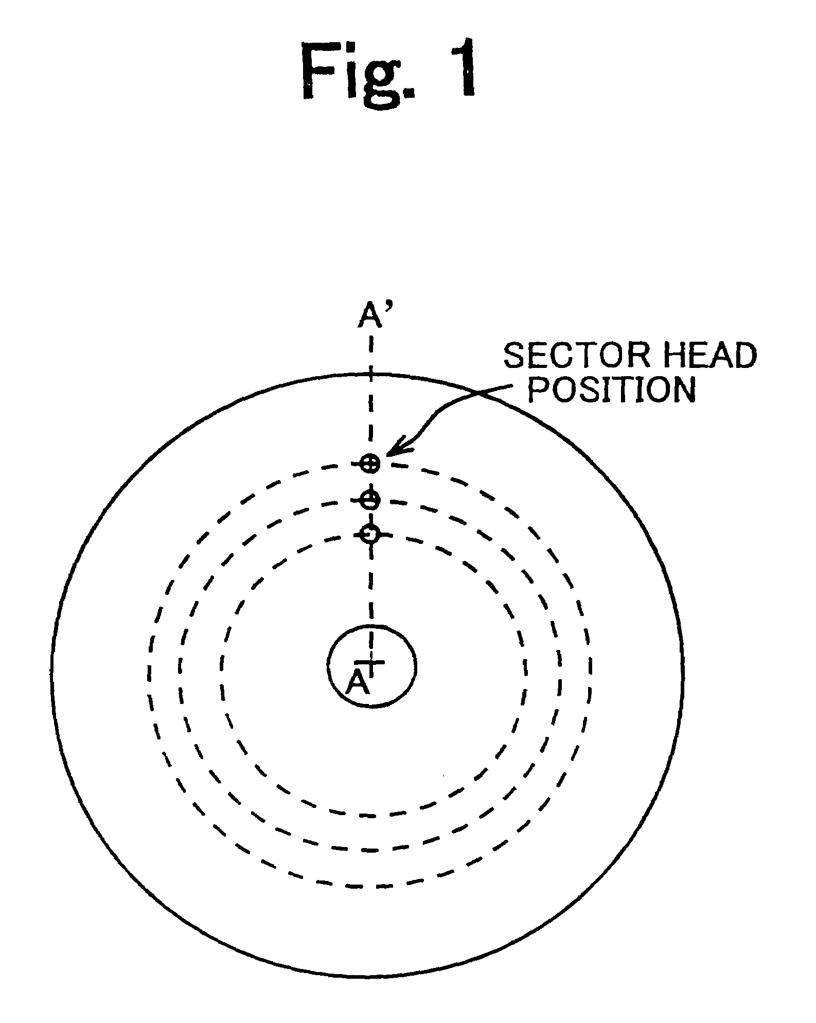
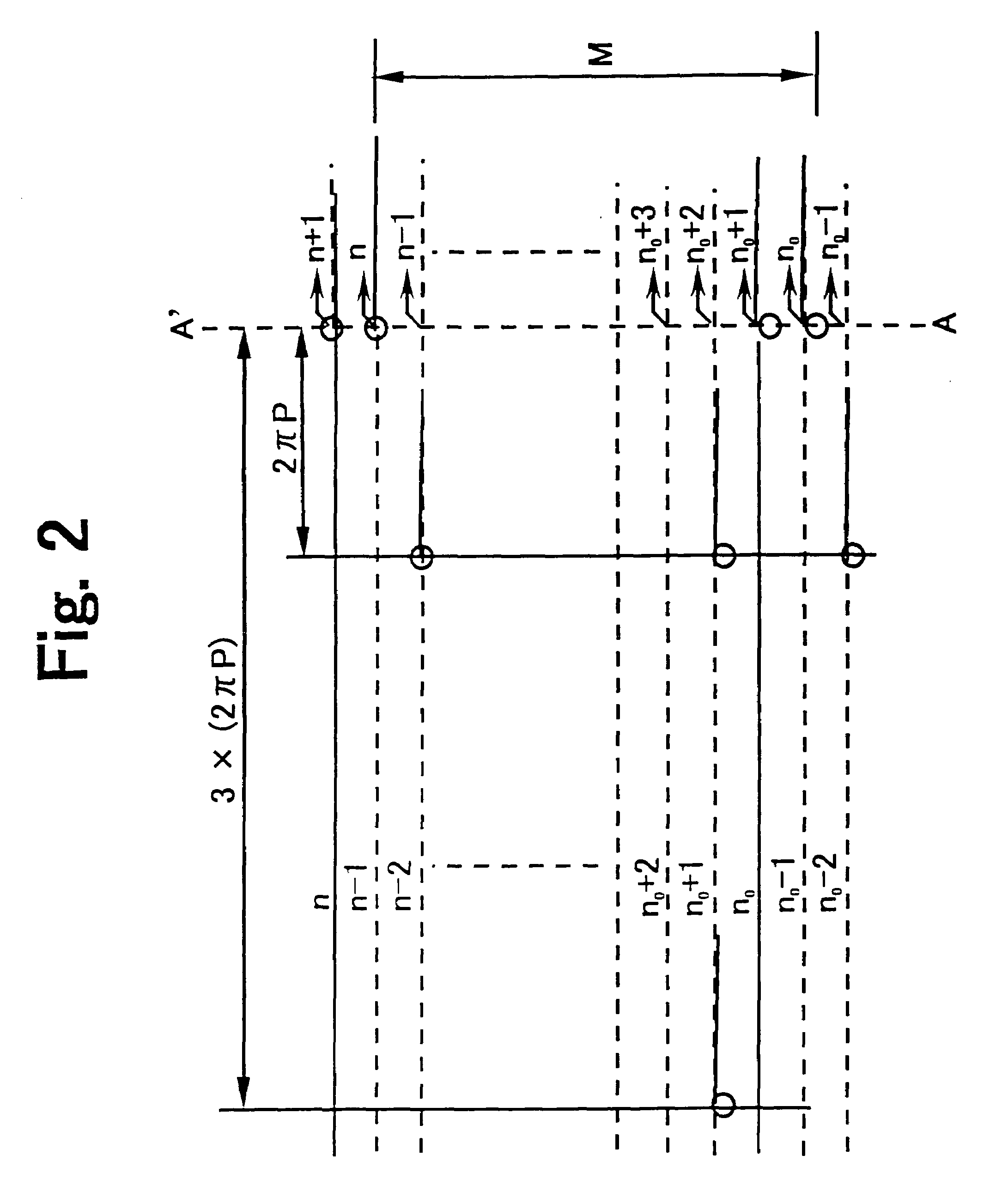
A CLV optical disc capable of recording the information with a constant linear velocity. In the CLV optical disc, plural lines of specified track exist in the predetermined data area, railroad length of the tracks is integer times of the length of a sector, the length of the sector on the specified tracks is 2×π×N times of a track pitch, the number N is a positive integral number, and head positions of the specified tracks are lined up on a predetermined radius line A—A′ at equal track intervals. Fixed-length track marks are arranged at equal physical length intervals along the information track formed in the state of a spiral. The track position information is obtained by detecting the track marks of the present and adjacent tracks. The CLV optical disc medium recording / reproducing apparatus can perform the seeking operation by use of the CPU and the other relevant units regardless of the operation of controlling the disc revolution number. In the CLV optical disc master board exposure, the CLV drive ordering pulse creating method can be realized by the spindle rotation ordering pulse train and the slider movement ordering pulse train.

Description

BACKGROUND OF THE INVENTION[0001]1. Field of the Invention[0002]The present invention relates to a CLV (Constant Linear Velocity) disc applied to optical disc medium, a format of the above-mentioned CLV optical disc, and an optical disc medium recording and reproducing apparatus, in particular, the CLV disc and the CLV disc format in the large capacitance optical disc apparatus capable of recording and reproducing the information on the optical disc medium.[0003]2. Discussion of the Background[0004]In order to raise the speed of accessing the information recorded on the optical disc media, it is necessary to control the speed of moving the optical head precisely and with high speed. When the optical disc apparatus receives the indication of accessing the information from the upper-ranked apparatus, the optical disc apparatus calculates the relationship between the logical number of the information and the physical position as shown by the track number or the sector number on the opt...

Claims


Application Information

Patent Timeline
Patent Type & Authority Patents(United States)
IPC IPC(8): G11B5/09G11B7/00
CPCG11B19/247G11B20/1217G11B2020/1232G11B2020/1238G11B2220/2537
Inventor WATANABE, HISAO
Owner RICOH KK
Learn More