Piston for internal combustion engine

An internal combustion engine and piston technology, which is applied in the field of pistons for internal combustion engines, can solve the problems of increased weight, severe friction between the piston and the cylinder, and the piston is stuck, and achieves the effect of reducing the skirt, realizing light weight, and preventing weight increase.

An internal combustion engine and piston technology, which is applied in the field of pistons for internal combustion engines, can solve the problems of increased weight, severe friction between the piston and the cylinder, and the piston is stuck, and achieves the effect of reducing the skirt, realizing light weight, and preventing weight increase.

CN100476185CInactive Publication Date: 2009-04-08HONDA MOTOR CO LTD

Image

  • Piston for internal combustion engine
  • Piston for internal combustion engine
  • Piston for internal combustion engine

Examples


Embodiment Construction

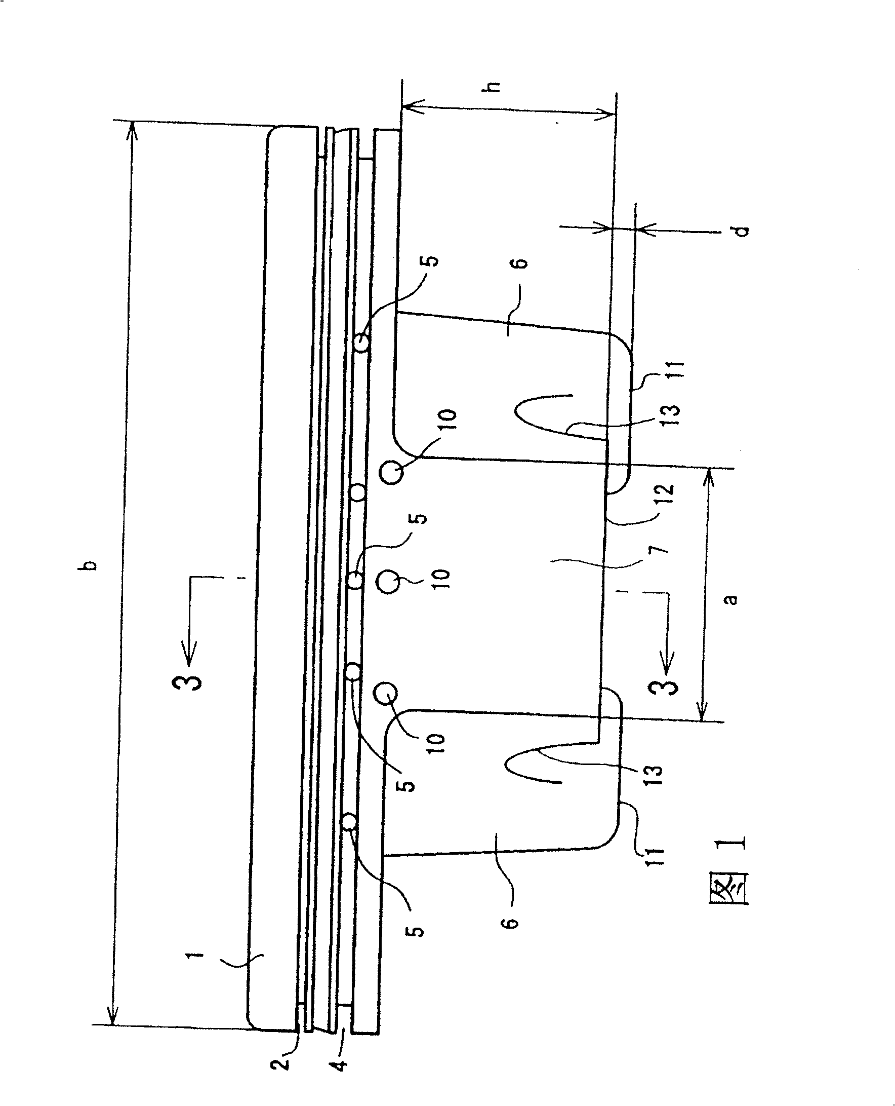
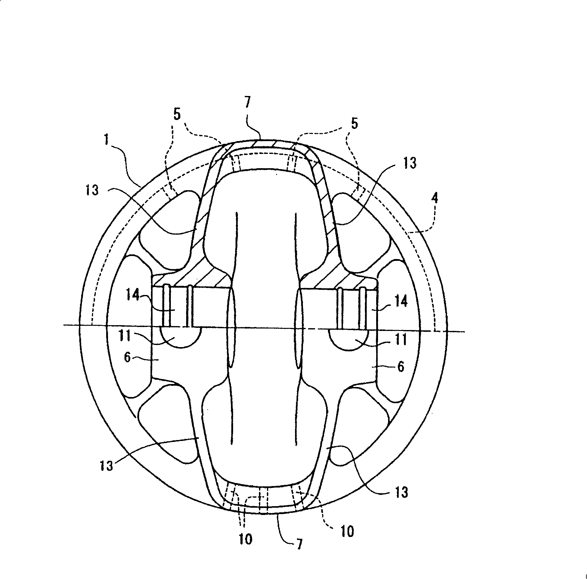
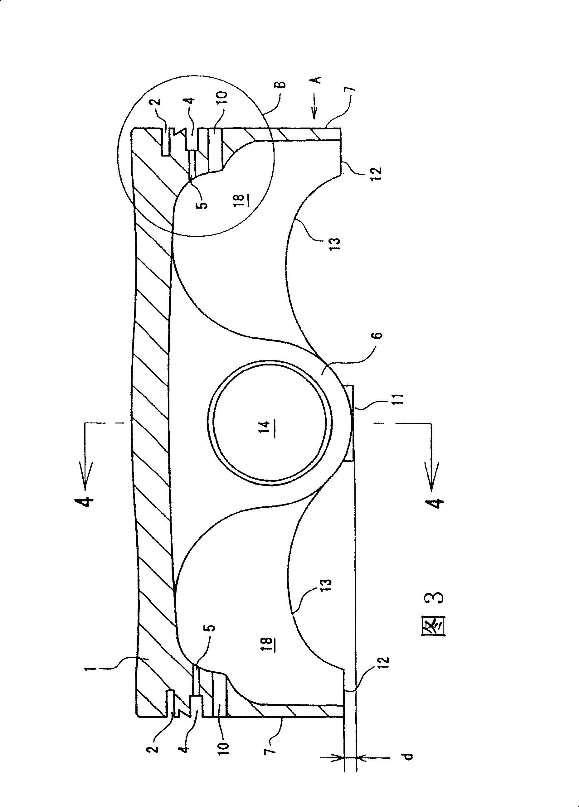
[0020] An embodiment will be described below with reference to the drawings. Fig. 1 is the front view (A arrow direction of Fig. 3) of the present embodiment piston, figure 2 It is a bottom view showing a half section from a piston pin seat to a skirt, and FIG. 3 is a cross-sectional view taken along line 3-3 in FIG. 1 . Fig. 4 is a sectional view taken along line 4-4 of Fig. 3 . Figure 5 It is an enlarged view of part B of FIG. 3 . Common symbols are used for parts common to the conventional example of FIG. 6 .

[0021] In FIG. 1, a first gas ring groove 2 is formed around the side surface of a crown 1, and an oil ring groove 4 is formed below it. On the bottom of the oil ring groove 4 , oil supply holes 5 are formed to penetrate inside and outside at appropriate intervals, and oil is supplied from the inner side of the piston to the surface side through the oil supply holes 5 . A pair of piston pin seat portions 6 and a skirt portion 7 are formed at the bottom of the cr...


PUM


Abstract

To form an internal combustion engine piston for high speed rotation by realizing a lightweight, compact structure. A top ring groove 2 and an oil ring groove 4 are formed in a circumferential part of a crown part 1, and lubricating holes 5 are provided at inner parts of the oil ring groove 4. A pair of piston boss parts 6 are provided at mutually facing positions under the crown part 1 to be continuous with it, and a skirt part 7 is provided at 90 DEG C. to it. A lower end 12 of the skirt part 7 is set above a lower end 11 of the piston boss part 6, and lubricating holes 10 are provided above the skirt part 7, and under and close to the oil ring groove 4.

Description

technical field [0001] The present invention relates to a piston for an internal combustion engine, and more particularly to a piston for an internal combustion engine suitable for high rotational speed and compactness. Background technique [0002] Existing pistons for internal combustion engines have a crown, a piston pin seat integrally formed with the crown, and a pair of skirts oppositely arranged, and grooves for piston rings are formed around the crown (as an example, refer to Japan Real Fair 7-7570). FIG. 6 shows such a conventional structure. A first gas ring groove 2, a secondary ring groove 3, and an oil groove 4 are provided around the crown portion 1, and piston rings omitted from the figure are respectively fitted in them. The bottom of the oil ring groove 4 is formed with an oil supply hole 5 penetrating inside and outside. [0003] Reference numeral 6 is a piston pin seat portion, 7 is a skirt portion, and the lower end of the skirt portion 7 extends downwa...

Claims


Application Information

Patent Timeline
08 Apr 2009
Publication
CN100476185C
IPC
F02F3/00; F01M9/00; F01M1/06; F01M11/02; F16J1/00; F16J1/08; F16J1/09; F16J1/16
CPC
F02F3/00; F01M2011/025; F16J1/08
Inventors
ι‡Žζ‘ζ˜Žε²; 志村康雄