Roll core and electrode body manufacturing method using same

A manufacturing method and electrode body technology, which can be applied in the manufacture of secondary batteries, winding/folding electrodes, battery electrodes, etc., can solve the problems of the deterioration of the quality of the electrode body, the tearing of the separator, and the increase in the cost of the winding core, and can suppress the damage to the ring. , The effect of preventing slippage and preventing quality degradation

Active Publication Date: 2009-04-08
MAXELL HLDG LTD
View PDF10 Cites 0 Cited by
  • Summary
  • Abstract
  • Description
  • Claims
  • Application Information

AI Technical Summary

Problems solved by technology

Therefore, in Patent Documents 1 to 3, the positional relationship between the positive electrode and the negative electrode is shifted due to the slip of the separator during winding, resulting in a decrease in the quality of the electrode body.
[0009] On the other hand, in Patent Documents 4 and 5, the diaphragm is clamped and fixed by the divided winding core to prevent the above-mentioned sliding of the diaphragm. are squeezed at the same time, so the diaphragm may be torn
Moreover, Patent Documents 4 and 5 may cause cost up of winding cores due to their complex structures.

Method used


Image

  • Roll core and electrode body manufacturing method using same
  • Roll core and electrode body manufacturing method using same
  • Roll core and electrode body manufacturing method using same

Examples


Embodiment Construction

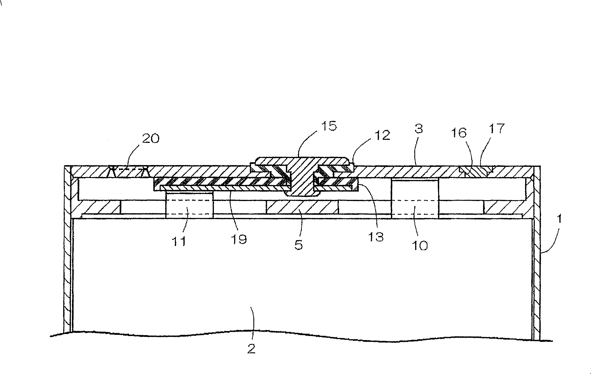
[0027] exist image 3 and Figure 4 Among them, the thin and sealed rectangular battery of the present invention comprises: a bottomed square battery case 1 with long left and right lateral openings; an electrode body 2 and a non-aqueous electrolyte contained in the battery case 1; the opening of the battery case 1 is blocked The upper left-right laterally long cover 3 and the plastic insulator 5 disposed inside the cover 3 are provided. The battery case 1 is a clad material made of nickel and aluminum, which is deep-drawn to form a thin case that is long in the vertical direction. The left and right width of the battery case 1 is 34 mm, the vertical height is 50 mm, and the front and rear thickness is 3.8 mm.

[0028] The electrode body 2 is formed by spirally winding a strip-shaped separator 9 made of a microporous polyethylene film (polyethylene film) between the strip-shaped positive electrode 6 and the strip-shaped negative electrode 7 . After being wound, the electrod...


PUM

PropertyMeasurementUnit
widthaaaaaaaaaa
sizeaaaaaaaaaa

Abstract

The present invention obtains a winding core having relatively simple structure capable of clipping and fixing a separator. The winding core 21 comprises an outer axis 22 on which a positive electrode 6, a negative electrode 7, and a separator 9 are wound, an inner axis 25 to fix the separator 9, and a receptacle axis 26 in which an insertion part 35 is engaged at the tip part 25b of the inner axis 25. The outer axis 22 has a space 23 opened at one end and the inner axis 25 is arranged in the space 23. The inner axis 25 has an inner axis slit 29 opened at the tip. The outer axis 22 has an outer axis slit 27 opposed to the inner axis slit 29. Separators 9, 9 piled in two are introduced in the inner axis slit 29 through the outer axis slit 27 and when the insertion part 35 of the receptacle axis 26 is engaged at the tip part 25b of the inner axis 25, the separator 9 is clipped and fixed by the closed inner slit 29.

Description

technical field [0001] The present invention relates to a winding core for manufacturing an electrode body contained in a battery case or the like of a lithium ion battery and a method for manufacturing an electrode body using the winding core. Background technique [0002] Patent Documents 1 to 5 disclose a method of manufacturing an electrode body in which a positive electrode, a negative electrode, and a separator are wound in a state where a strip-shaped separator is sandwiched between a strip-shaped positive electrode and a strip-shaped negative electrode by rotating a winding core. onto the aforementioned winding core to manufacture an electrode body. [0003] Patent Document 1: Japanese Patent Laying-Open No. 8-153519 (paragraphs 0009-0010, Figure 6-1 0) [0004] Patent Document 2: Japanese Unexamined Patent Publication No. 2003-282136 (paragraph 0017, figure 1 ) [0005] Patent Document 3: Japanese Patent No. 536391 (paragraph 0046, figure 2 ) [0006] Patent...

Claims


Application Information

Patent Timeline
Patent Type & Authority Patents(China)
IPC IPC(8): H01M10/38H01M10/40H01M10/04H01M6/16H01M10/0587
CPCY02E60/122H01M4/139H01M10/0587Y02E60/10Y02P70/50H01M10/0409H01M10/0431
Inventor 竹轮光博高原知新服部浩
Owner MAXELL HLDG LTD
Why Eureka
Try Eureka