Combined conveying device

A conveying device and a combined technology, applied in the field of machinery, to achieve the effects of reducing maintenance costs, improving service life, and uniform force

Pending Publication Date: 2020-09-25
HEILONGJIANG INST OF PASTURAGE MECHANISATION
View PDF0 Cites 0 Cited by
  • Summary
  • Abstract
  • Description
  • Claims
  • Application Information

AI Technical Summary

Problems solved by technology

[0003] In order to overcome the deficiencies existing in the use of the existing conveying device, the present invention provides a combined conveying device, which solves the phenomenon of deviation of the rubber sheet due to deformation and wear, improves the service life of the rubber sheet, and reduces the Maintenance costs

Method used


Image

  • Combined conveying device
  • Combined conveying device
  • Combined conveying device

Examples


Embodiment Construction

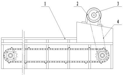
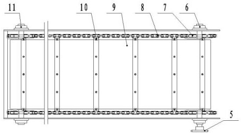
[0016] The present invention will be further described below in conjunction with the accompanying drawings. The present invention provides a combined conveyor belt, including a frame (1), a motor (2), a motor sprocket (3), a transmission chain (4), and a transmission sprocket (5 ), active transmission (6), intermediate sprocket (7), conveyor chain (8), conveyor belt (9), connecting bolts (10), passive transmission (11).

[0017] When working, the material is placed on the conveyor belt (9), the motor (2) on the frame (1) is started, the motor sprocket (3) rotates, and the drive chain (4) drives the drive sprocket (5) to work , at this time, the transmission sprocket (5) transmits power to the driving transmission (6), and the driving transmission (6) starts to work, driving the two intermediate sprockets (7) on the driving transmission (6) to rotate , and drive the two intermediate sprockets (7) on the passive transmission device (11) to rotate through two sets of conveyor cha...


PUM


Abstract

The invention discloses a combined conveying device. The combined conveying device comprises a rack, a motor, a motor chain wheel, a transmission chain, a transmission chain wheel, a driving transmission device, middle chain wheels, conveying chains, a conveying belt, connecting bolts and a driven transmission device. During operation, materials are placed on the conveying belt, the motor on the rack is started, the motor chain wheel rotates, the transmission chain wheel is driven to work through the transmission chain, at the moment, the transmission chain wheel transmits power to the drivingtransmission device, the driving transmission device starts to work, and the two middle chain wheels on the driving transmission device are driven to rotate, the two middle chain wheels on the driventransmission device are driven to rotate through the two groups of conveying chains, two groups of closed rotating chains are formed, and at the moment, the conveying belts connected to the two groups of conveying chains are driven to work with the rotation of the two groups of conveying chains, so that the materials placed on the conveying belt are continuously conveyed.

Description

technical field [0001] The invention relates to the field of machinery, in particular to a combined conveying device for conveying materials. Background technique [0002] At present, the known conveying device mainly adopts a single rubber plate conveying method. Since the side of the rubber plate is not restrained, it will be deformed after a long time of work; at the same time, due to the action of the material, the side of the rubber plate will be worn, which will Affect the transmission of the rubber sheet, causing it to be unevenly stressed, and deviation occurs, resulting in insufficient material delivery, which directly affects the next process. Therefore, the existing conveying device needs to be frequently adjusted for the rubber sheet. This not only reduces the production efficiency, but also shortens the service life of the rubber sheet and increases the production cost. Contents of the invention [0003] In order to overcome the deficiencies existing in the...

Claims


Application Information

Patent Timeline
Patent Type & Authority Applications(China)
IPC IPC(8): B65G17/48B65G17/06B65G17/38B65G23/06
CPCB65G17/06B65G17/38B65G17/48B65G23/06
Inventor 曹明璐李爱华王敦军邱岳巍冯骥强朱洪林刘玉峰杨宝珍
Owner HEILONGJIANG INST OF PASTURAGE MECHANISATION
Why Eureka
Try Eureka