
LCD panel and powering method thereof

A liquid crystal panel and electrical method technology, applied in nonlinear optics, instruments, optics, etc., can solve the problems of increasing manufacturing cost and high process difficulty, and achieve the effects of reducing difficulty, expanding viewing angle width, and reducing manufacturing cost

Active Publication Date: 2009-04-29
BOE TECH GRP CO LTD
View PDF7 Cites 0 Cited by
  • Summary
  • Abstract
  • Description
  • Claims
  • Application Information

AI Technical Summary

Problems solved by technology

[0006] The defect of the existing technology is that: the existing VA technology, IPS technology or FFS technology etc. divide a pixel or sub-pixel into multiple domains, each domain has a specific alignment orientation, different alignment orientations of multiple domains, Make the liquid crystal arrangement and orientation of the entire pixel comprehensively converge from each viewing angle to meet the viewing angle requirements of each direction
However, the technical difficulty of this technical solution is very high, which increases the manufacturing cost

Method used


Image

  • LCD panel and powering method thereof
  • LCD panel and powering method thereof
  • LCD panel and powering method thereof

Examples


Embodiment 1

[0029] This embodiment provides a liquid crystal panel power-on method based on the liquid crystal panel of the present invention, such as Figure 6 shown, including:

[0030] Step 101 , after receiving a power-on command, power on one sub-electrode in each sub-pixel electrode of the liquid crystal panel.

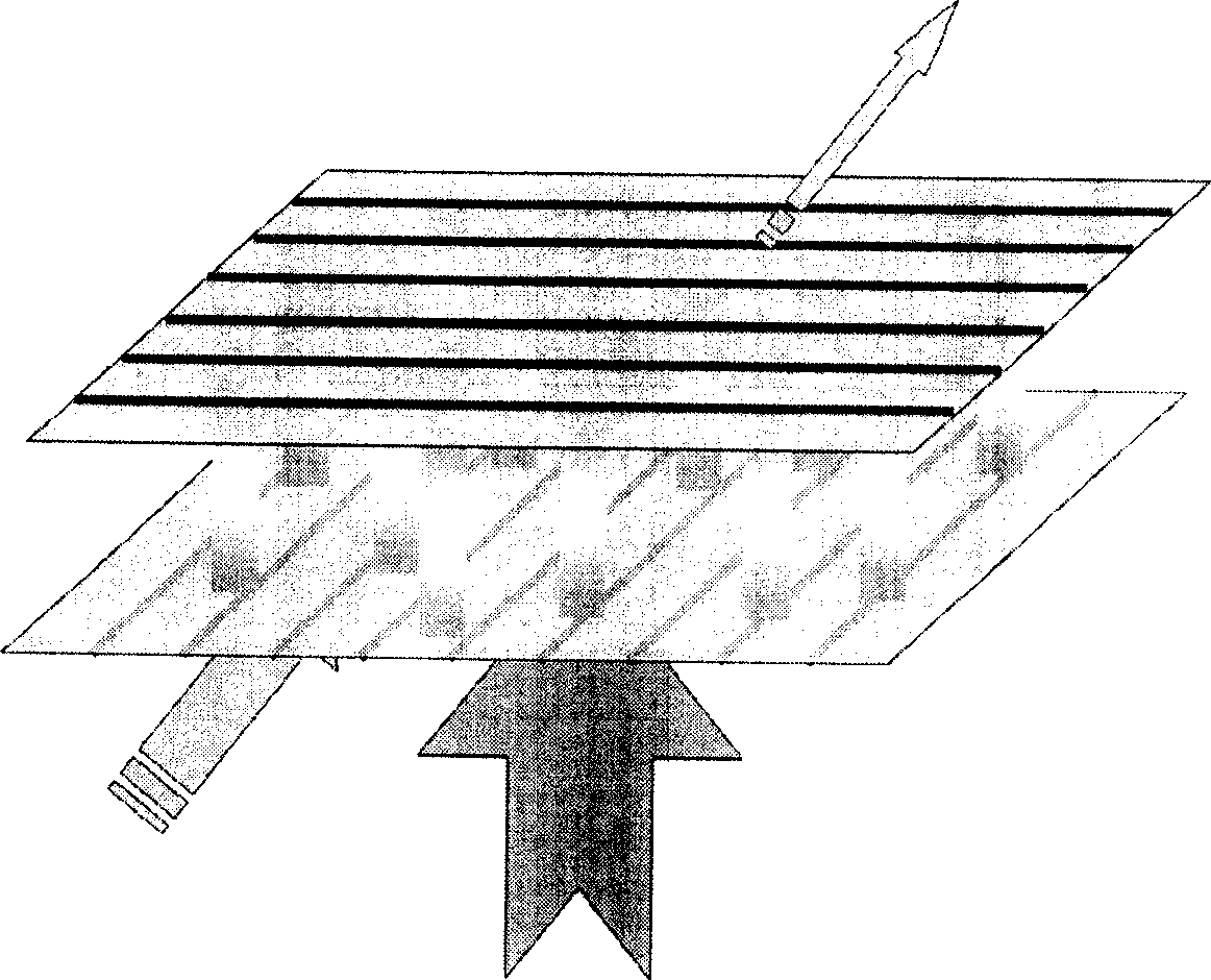
[0031] Wherein, which sub-electrode is selected as the first sub-electrode to be powered on has no decisive influence on the purpose of achieving a wide viewing angle, and therefore, no limitation is made in this embodiment. However, it is preferable that the first electrified sub-electrodes of adjacent sub-pixels be symmetrical. For example, if Figure 7 As shown in , the partial electrodes marked with shaded grids are powered on at the current moment.

[0032] Step 102, when the preset power-on interval time arrives, power off the sub-electrode that has been powered on, and power on another sub-electrode adjacent to the sub-electrode that was powered on just now.

[0...

Embodiment 2

[0041] This embodiment provides another liquid crystal panel power-on method, and the only difference from Embodiment 1 is: when the sub-electrodes in each sub-pixel electrode are cycled and sequentially powered on, only all the sub-pixel electrodes in each sub-pixel electrode Part of the sub-electrodes in the sub-electrodes are powered on in turn.

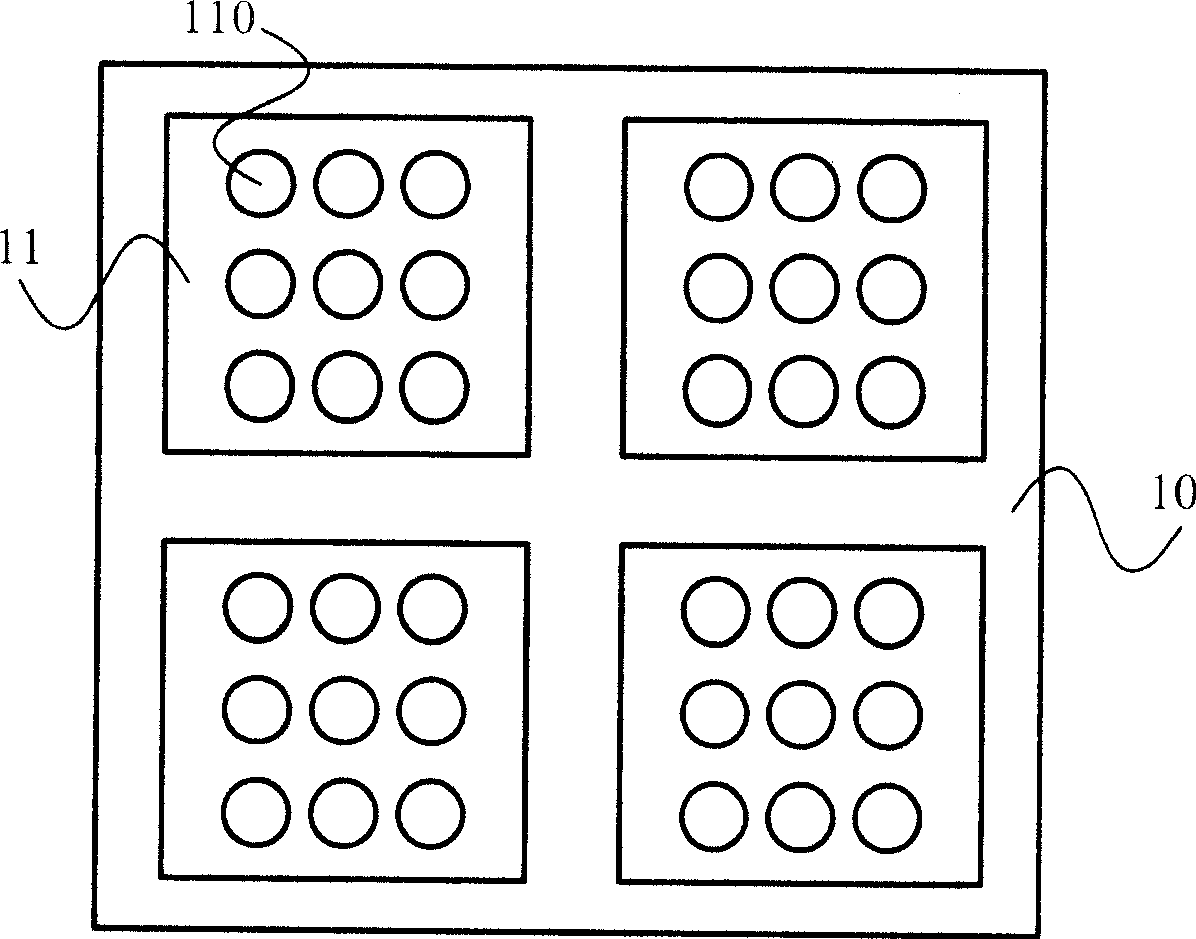
[0042] For example, if Figure 8 As shown, the sub-pixel electrodes of the sub-pixel 11 include 9 sub-electrodes 60-68. The sub-electrodes 64 , 65 and 66 are not always powered on, but only the sub-electrodes 60 , 61 , 62 , 63 , 67 and 68 are cyclically powered on.

[0043] Through the method described in this embodiment, the user can cycle and sequentially power on only some sub-electrodes according to the requirement of the viewing angle width of the liquid crystal panel. For example, if only the viewing angle width of the lower part of the liquid crystal panel is required in practical applications, only the sub-electrodes at ...


PUM


Abstract

The invention relates to a liquid crystal panel and a charging method, wherein the liquid crystal panel comprises an array substrate, the array substrate is provided with sub-pixel, each sub-pixel is correspondingly provided with the sub-pixel electrode, the sub-pixel electrode comprises a plurality of sub-electrodes, a plurality of sub-electrodes are dispersedly arranged in the area range of the sub-pixel. The method comprises: when receiving a charging instruction, one sub-electrode of each sub-pixel electrode in the liquid crystal panel is charged; when the scheduled charging interval time is arrived, the charged sub-electrode is power off, another sub-electrode neighboring to the sub-electrode is charged; the rest may be deduced by analogy, the sub-electrode of each sub-pixel electrode is circularly charged in turn. Through the invention, the purpose of expanding the visual angle width of the liquid crystal panel is achieved, and as the pixel needs not be disparted, the difficulty of the manufacturing technique is reduced, and the manufacturing costs are reduced.

Description

technical field [0001] The invention relates to a liquid crystal panel, in particular to a liquid crystal panel capable of realizing a wide viewing angle without pixel division, and a power-on method of the liquid crystal panel. Background technique [0002] The existing liquid crystal panel mainly includes an array substrate, a color filter substrate, and liquid crystal sandwiched between the array substrate and the color filter substrate. As the application fields of liquid crystal displays continue to expand, the requirements for liquid crystal displays also continue to increase. The existing twisted nematic (Twisted Nematic, referred to as: TN) type liquid crystal display has a narrow viewing angle, the reasons are as follows figure 1 , 2 As shown, in the normal white mode, due to the inconsistency of the orientation of the liquid crystal molecules observed from various angles, when the voltage is applied, the liquid crystals in the pixel are arranged vertically to the...

Claims


Application Information

Patent Timeline
Patent Type & Authority Patents(China)
IPC IPC(8): G02F1/1343G02F1/133
Inventor 张卓史冉邵喜斌
Owner BOE TECH GRP CO LTD
Features
  • Generate Ideas
  • Intellectual Property
  • Life Sciences
  • Materials
  • Tech Scout
  • Unparalleled Data Quality
  • Higher Quality Content
  • 60% Fewer Hallucinations
Learn More