Sanitary insert unit

An insertion device, sanitary technology, applied in the direction of indoor sanitary plumbing installations, water supply installations, buildings, etc.

Active Publication Date: 2009-05-06
NEOPERL
View PDF3 Cites 0 Cited by
  • Summary
  • Abstract
  • Description
  • Claims
  • Application Information

AI Technical Summary

Problems solved by technology

[0003] In the case of such an insertion device which combines a flow regulator on the inflow side and a w

Method used


Image

  • Sanitary insert unit
  • Sanitary insert unit

Examples


Embodiment Construction

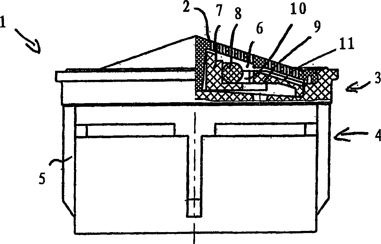
[0016] The hygienic plug-in device designated as a whole by 1 has a pre-sieve 2 , a flow regulator 3 and a water flow regulator 4 detachably interconnected with its housing 5 .

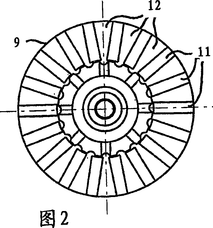
[0017] figure 1 A partially cut-away side view of the insertion device 1 is shown. An inner cavity 6 is formed below the substantially conical pre-filter 2, and a flow regulator 3 is arranged in the inner cavity. The flow regulator 3 has a central core area 7 which is surrounded by an annular throttle body 8 . Between the throttle body 8 and a radially inwardly rising bevel 9 , a control gap 10 is formed in the outer edge region of the flow regulator 3 , which is in flow connection with the water flow regulator 4 arranged below it.

[0018] The central core area 7, the throttle body 8 and the rising slope 9 are dimensioned such that the cross-sectional profile of the flow regulator 3 and the cross-sectional profile of the pre-filter 2 are basically shape-adapted, wherein the rising slope 9 and the f...


PUM


Abstract

The invention relates to a hygienic insertion device (1) for insertion into a water valve, comprising a substantially conical pre-sieve (2), behind which a flow rate is arranged in the flow direction regulator (3) and a water flow regulator (4). Wherein, the flow regulator (3) is basically arranged in the inner chamber (6) of the insertion device (1) defined on the upper side by the pre-filter (2) and the flow regulator (3) has a connection with the pre-filter The cross-sectional profile of the web (2) is essentially a shape-adapted cross-sectional profile. The flow regulator (3) has a radially inwardly rising ramp (9) in an outer, especially annular edge region, which leads to a control slot (10) or similar to the flow regulator (4) The through-flow opening is in the through-flow connection, and the ascending slope (9) and the pre-filter (2) are spaced apart from each other.

Description

technical field [0001] The invention relates to a hygienic insertion device for insertion into a water valve, comprising a substantially conical pre-sieve, behind which a flow regulator and a water flow regulator are arranged in the flow direction device. Background technique [0002] Hygienic insertion devices of the type mentioned at the outset are already known in various embodiments. Such an insertion device is usually inserted into an outlet nozzle which is detachably fastened to the sanitary water valve. An even, gentle, non-splashing water flow can be created with such an insertion device. [0003] In the case of such an insertion device, which combines an inflow-side flow regulator and an outflow-side water flow regulator, installation problems can arise due to structural dimensions. In particular, supplementary installations in water valves are problematic, which previously involved a plug-in device with only a flow regulator and no flow regulator, since the last...

Claims


Application Information

Patent Timeline
IPC IPC(8): E03C1/08
CPCE03C1/08E03C2001/026
Inventor 乌韦·措勒尔
Owner NEOPERL
Why Eureka
Try Eureka