Bidirectionally swinging mechanism for airspace engine

A technology for aerospace engines and motors, applied in the direction of engine components, turbine/propellant fuel delivery systems, charging systems, etc., can solve the problem of increasing the complexity of the mechanism, increasing the complexity of the pipeline layout, and not fully satisfying the attitude of the spacecraft and track state control requirements to achieve the effect of simplifying the function implementation and simplifying the layout

Active Publication Date: 2018-01-16
贵州航天朝阳科技有限责任公司
View PDF11 Cites 6 Cited by
  • Summary
  • Abstract
  • Description
  • Claims
  • Application Information

AI Technical Summary

Problems solved by technology

[0004] 1. A realization method of a left-right swing mechanism. The mechanism rotates under the drive of the rotating shaft, thereby driving the engine solenoid valve connected to it on the shaft to swing left and right, thereby realizing the change in the thrust direction of the engine; but this realization mechanism adopts an external The form of pipeline layout increases the complexity of pipeline layout. In addition, the mechanism can only realize the swing in one direction, which is not completely sufficient to meet the control requirements of spacecraft attitude and orbital state
[0005] 2. A numerically controlled universal swing mechanism, which swings in a transmission mode similar to hinged chains, thereby driving the engine solenoid valve connected to it to swing in all directions, thereby realizing changes in the engine thrust direction; but This kind of realization mechanism adopts the form of multiple hinge structures, which increases the complexity of the realization mechanism, and increases the difficulty of control in the swing direction and the complexity of pipeline layout.
[0006] There are still many limitations in the realization of aero-engine swing at this stage

Method used


Image

  • Bidirectionally swinging mechanism for airspace engine
  • Bidirectionally swinging mechanism for airspace engine
  • Bidirectionally swinging mechanism for airspace engine

Examples


Embodiment Construction

[0024] The technical solution of the present invention is further described below, but the scope of protection is not limited to the description.

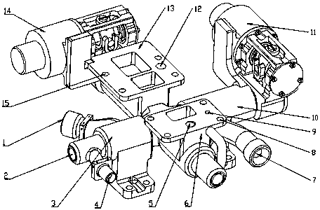
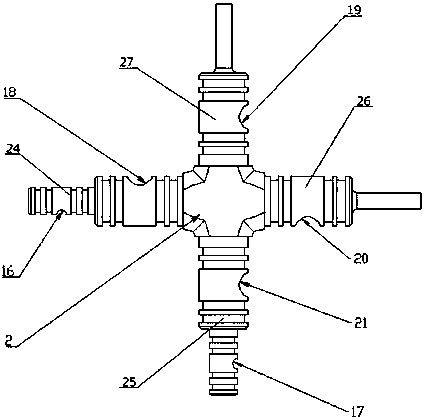
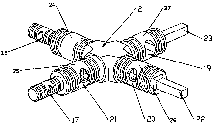
[0025] Such as Figure 1~3 Shown is a kind of two-way rocking mechanism that is used for aerospace engine, comprises cross 2, fixed bracket one 3, supports rotating block one 6, fixed bracket two 10, motor one 11, supports rotating block two 13 and motor two 14; The A-axis 24 and the C-axis 26 of the cross 2 are respectively fixedly provided with a fixed bracket 1 3 and a fixed bracket 2 10 for fixed connection with the base support frame, and the B-axis 25 and the D-axis 27 of the cross 2 are respectively fixedly arranged to be useful. The supporting rotating block one 6 and the supporting rotating block two 13 fixedly connected with the engine electromagnetic valve; the motor one 11 is fixedly connected with the fixed bracket two 10, and the power output end of the motor one 11 is connected with the load-bearing side arranged on ...


PUM


Abstract

The invention provides a bidirectionally swinging mechanism for an airspace engine. The A shaft and C shaft of a cross are respectively fixedly provided with a fixed support I and a fixed support II in fixed connection with a pedestal supporting frame; the B shaft and D shaft of the cross are respectively fixedly provided with a support rotation block I and a support rotation block II in fixed connection with solenoid valves of the engine; a motor I is fixedly connected with the fixed support II, and the power output terminal of the motor I is fixedly connected with a square load-bearing shaftI arranged on the outer end of the C shaft; and a motor II is fixedly connected with the support rotation block II, and the power output terminal of the motor II is fixedly connected with a square load-bearing shaft II arranged on the outer end of the D shaft. The bidirectionally swinging mechanism provided by the invention can realize swinging in two directions perpendicular to each other; through usage of internal pipelines on the cross, construction of the swinging mechanism and arrangement of engine pipelines are simplified; and the bidirectionally swinging mechanism can meet the requirement of the airspace engine for swinging movement in perpendicular directions under specific working conditions.

Description

technical field [0001] The invention relates to the technical field of aerospace engines, in particular to a two-way rocking mechanism for aerospace engines. Background technique [0002] With the continuous development of aerospace industry, aerospace engine is an indispensable product in aerospace industry, and its design and development are subject to strict requirements. Under normal circumstances, the aerospace engine is fixed on the support plate, and its thrust direction is also unchanged. However, due to the control requirements of the spacecraft attitude and orbital state, it will become a key point in the research field of the aerospace industry to change the thrust direction of the engine. focus. The current technical difficulties in the field of thrust direction change of aerospace engines are as follows: 1. The mechanism for realizing thrust change direction is complicated; Large, it is easy to bring greater vibration; Fourth, the generation of torque increase...

Claims


Application Information

Patent Timeline
Patent Type & Authority Applications(China)
IPC IPC(8): F02C7/22
Inventor 张鹏贺迪华王浩冯思锐马志仓刘忠黄华平何勇
Owner 贵州航天朝阳科技有限责任公司
Why Eureka
Try Eureka