Crank link rod mechanism with variable length link rod
A crank-link mechanism and connecting rod technology, which is applied in the direction of mechanical equipment, belts/chains/gears, transmission devices, etc., can solve problems such as no solutions, no attention to it, and pressure effects
- Summary
- Abstract
- Description
- Claims
- Application Information
AI Technical Summary
Problems solved by technology
Method used
Image
Examples
Embodiment 1
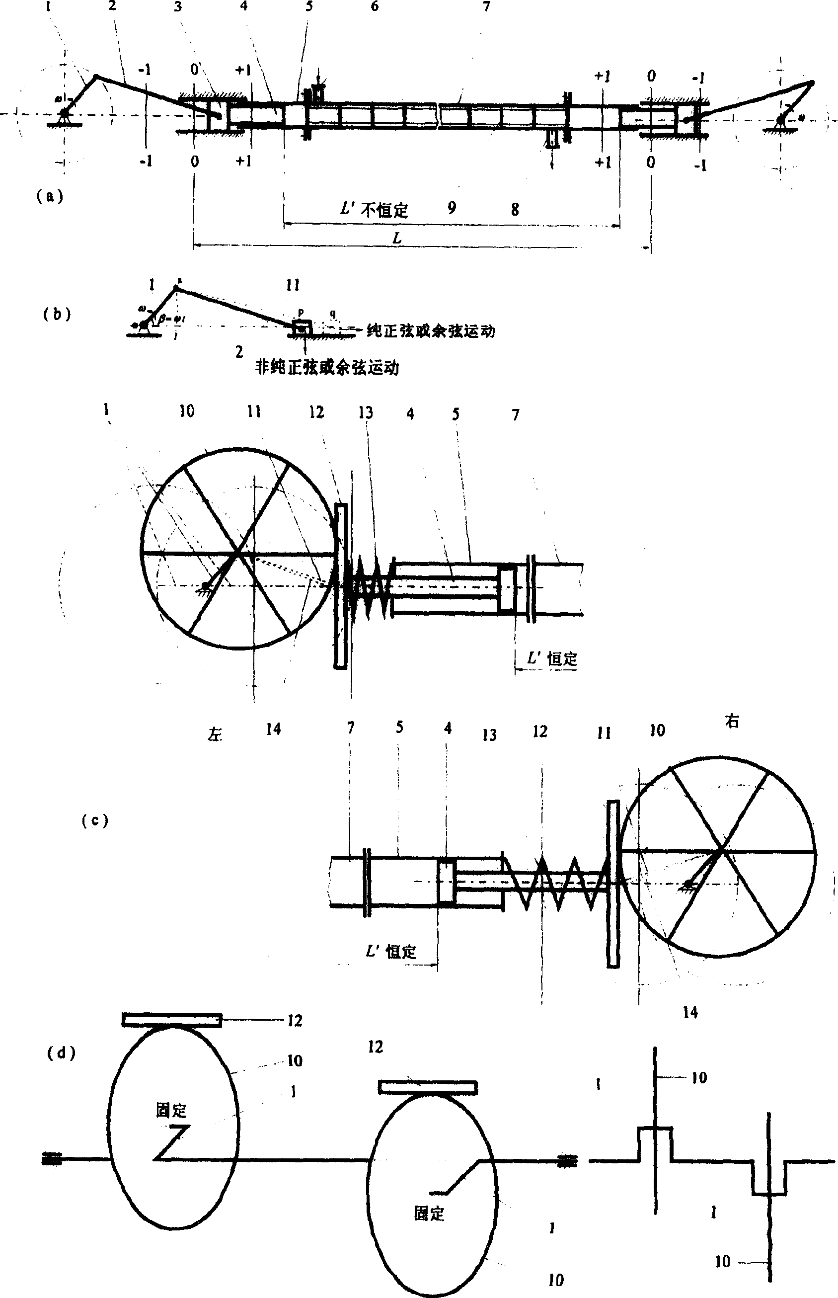
[0034] Embodiment 1, the device 7 is sealed and fixedly connected with the piston guide tube 5 through flanges, bolts, and gasket assemblies, the piston 4 is sealed and movable with the piston guide tube 5 through the sealing element, and the piston rod of the piston 4 is in contact with the contact piece 12 Vertical fixed connection, the piston rod is covered with a spring 13 (compression spring), one end of the spring 13 bears on the outer end of the piston guide cylinder 5, and the other end bears on the contact piece 12, so as to ensure that the contact piece 12 is in tangential contact with the push wheel 10 all the time, and the push wheel The radius of 10 is equivalent to the connecting rod length of the common crank linkage mechanism, which is greater than the length of the crank 1, and the geometric center of the push wheel 10 is fixedly connected with the end of the crank 1. The crank 1 is driven to rotate by a power device (such as a motor), and the crank 1 drives th...
Embodiment 2
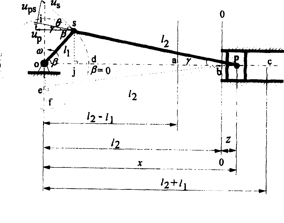
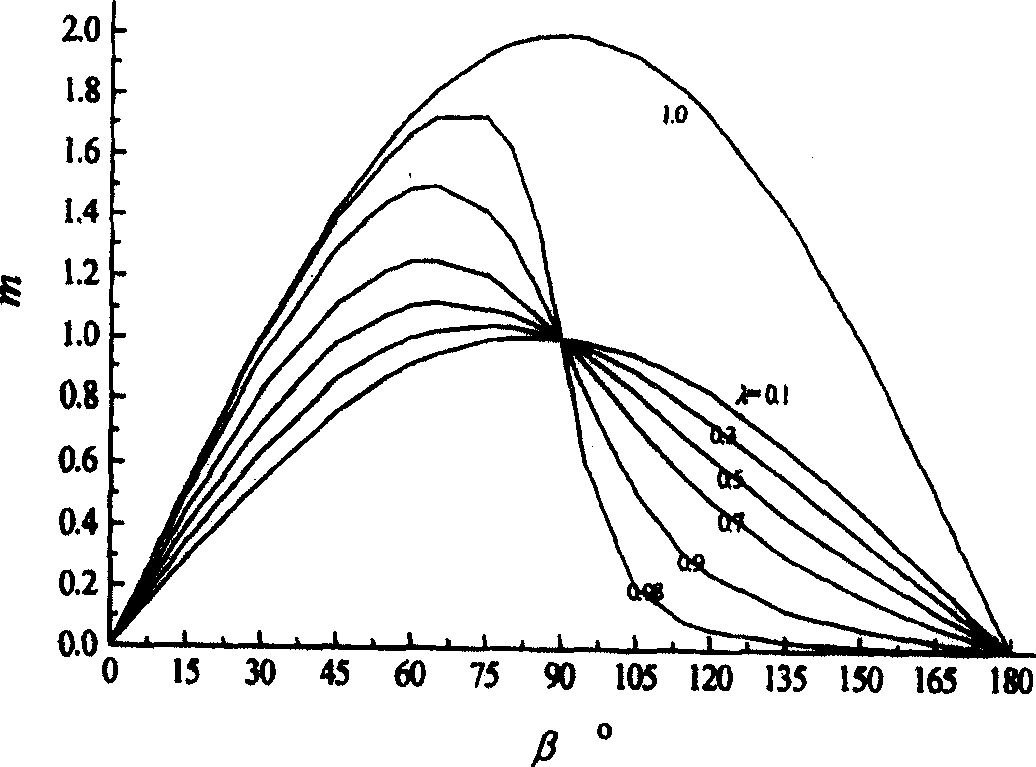
[0036]Embodiment 2, adjust the parameters such as the size and rotational speed of the crank 1 and the connecting rod 2 so that the pistons can obtain the required movement law or the distance between the inner end surfaces of the two pistons can be changed according to the required law. From the motion analysis below, it can be seen that different lengths of the crank 1 and connecting rod 2 form different motion laws, and designing different lengths of the crank 1 and connecting rod 2 according to actual needs can make the piston 4 obtain different motion laws. In addition, from the following formula (10) and Figure 16 It can be seen that the smaller η is (η=λ / λ'=(l 1 / l 2 ) / (l 1 ' / l 2 ')=(l 1 l 2 ') / (l 1 'l 2 )), the smaller the change δ of the distance between the inner faces of the two pistons 4 is. Accordingly, if the push wheel 10 is not used and the δ is desired to be small, a smaller η design can be adopted. where l 1 , l 1 ' are the lengths of the cranks 1...
Embodiment 3
[0037] Example 3, any with l 1 is the length of crank 1, with l 2 2 + l 1 2 sin 2 β = l 2 2 + l 1 2 sin 2 ωt The crank-and-rod mechanism formed by the length of the connecting rod 2 can implement the crank-and-rod mechanism with variable length of the connecting rod, wherein l 1 is the length of crank 1, l 2 Be the length of fixed-length connecting rod 2 of ordinary crank-link mechanism, equal to the radius of push wheel 10 at this moment, β is the position angle of certain instant crank 1, ω is the angular velocity of crank 1, t is time.
[0038] The motion analysis will be car...
PUM
 Abstract
Description
Claims
Application Information
 - R&D
- Intellectual Property
- Life Sciences
- Materials
- Tech Scout
- Unparalleled Data Quality
- Higher Quality Content
- 60% Fewer Hallucinations
Browse by: Latest US Patents, China's latest patents, Technical Efficacy Thesaurus, Application Domain, Technology Topic, Popular Technical Reports.
© 2025 PatSnap. All rights reserved.Legal|Privacy policy|Modern Slavery Act Transparency Statement|Sitemap|About US| Contact US: help@patsnap.com


