An energy-saving quayside crane system with double trolleys
A double trolley, traversing technology, which is applied in the directions of walking bridge cranes, hoisting equipment braking devices, load hanging elements, etc. The rope is simple, the structure is simplified, and the cost is reduced.
- Summary
- Abstract
- Description
- Claims
- Application Information
AI Technical Summary
Problems solved by technology
Method used
Image
Examples
Embodiment 1
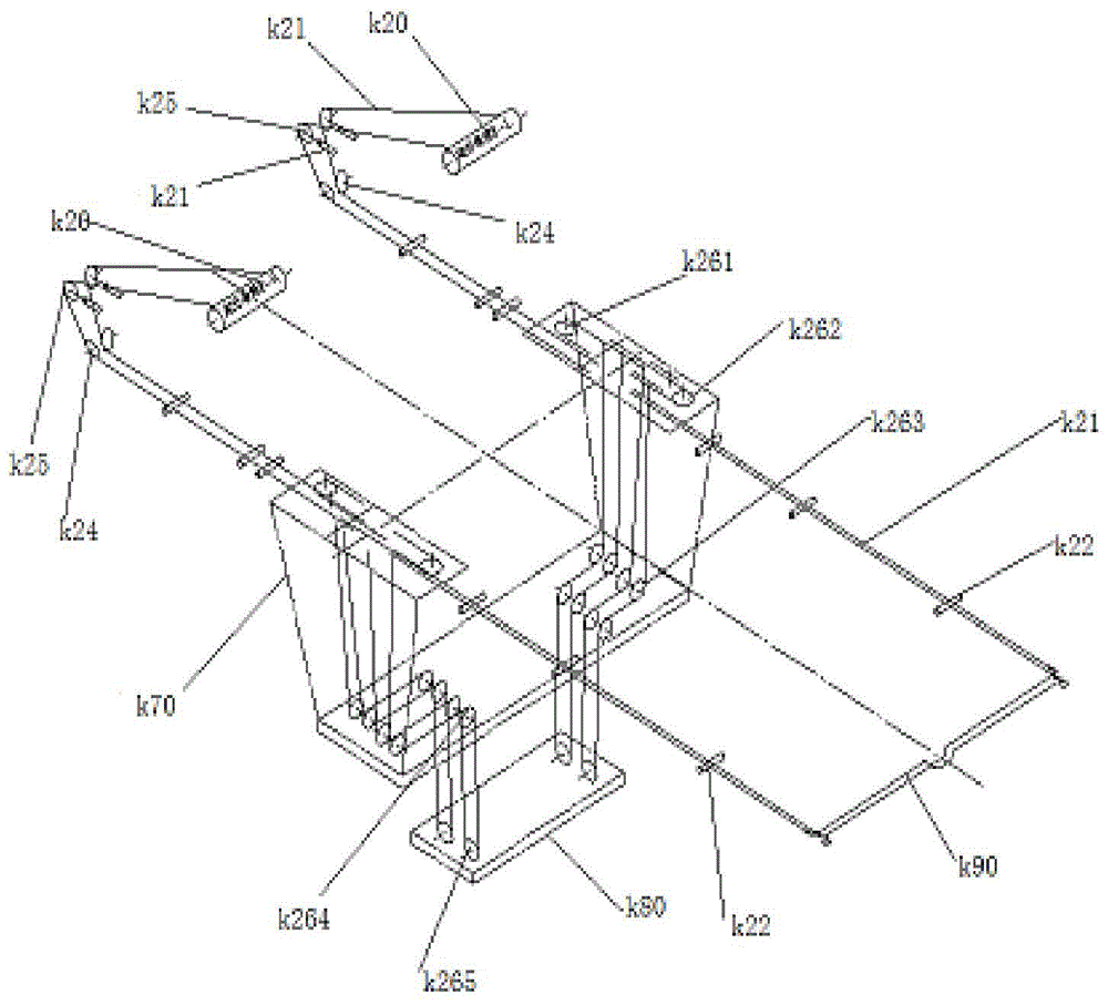
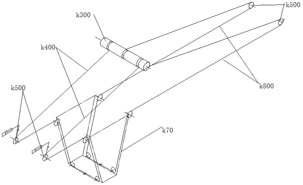
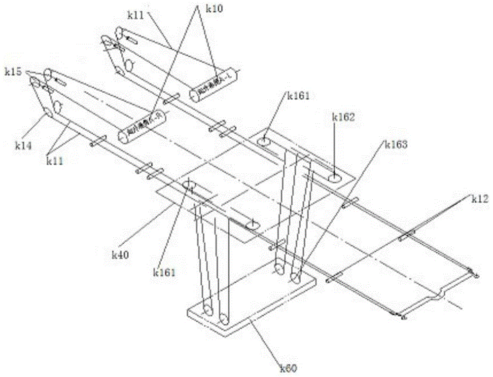
[0069] This embodiment provides a winding system that can be used for upper and lower trolleys in a through-type double-car energy-saving quay crane system. The winding system can be used in the cooperative use of the through-type double-car and quay crane. Specifically, the winding system is suitable for use in the following girder structures, such as Figure 7 , Figure 8 with Figure 21 As shown, the girder structure includes a first girder s1 and a second girder s2 arranged in parallel; a first guide rail s3 and a second guide rail s4 are provided on the opposite inner sides of the first girder s1 and the second girder s2, so The first guide rail s3 and the second guide rail s4 jointly form a first guide rail structure supporting the operation of the upper trolley k40; the outside of the first beam s1 and the second beam s2 are provided with a third guide rail s5 and a second guide rail. The four guide rails s6, the third guide rail s5 and the fourth guide rail s6 jointl...
Embodiment 2
[0098] Such as Figure 10 As shown, this embodiment provides a potential energy compensation system in a traversable double-car energy-saving quayside crane system, including a balance weight a5, a potential energy compensation winding system a4, and a potential energy compensation wire rope a3.
[0099] Wherein, the lower end of the potential energy compensation winding system a4 is connected to the balance weight a5 for transmitting driving force to make the balance weight a5 rise or fall; one end of the potential energy compensation wire rope a3 is connected to the potential energy compensation winding system a4 The upper end and the other end are adapted to be connected with a driving force source for transmitting the driving force to make the potential energy compensation winding system a4 act, so that the balance weight a5 rises or falls.
[0100] The potential energy compensation system of this embodiment also includes a lifting drum a1 for the lifting wire rope a7 and ...
Embodiment 3
[0121] As an alternative form of the potential energy compensation system in embodiment 2, this embodiment provides a potential energy compensation system, in this embodiment, such as Figure 11 As shown, the potential energy compensation system is provided in two sets, which are respectively arranged on the left side and the right side of the trolley spreader a6, and the four potential energy compensation steel wire ropes of each set of the potential energy compensation system pass through the redirection pulley Winding on the lifting drum on the corresponding side, that is, the potential energy compensation steel wire rope on the left side of the spreader is wound on the first lifting drum through the redirection pulley, and the potential energy compensation steel wire rope on the right side of the spreader is Winding to the pulley on the second lifting drum.
[0122] It should be noted that, in each of the potential energy compensation systems in this embodiment, the ratio ...
PUM
 Abstract
Description
Claims
Application Information
 - R&D
- Intellectual Property
- Life Sciences
- Materials
- Tech Scout
- Unparalleled Data Quality
- Higher Quality Content
- 60% Fewer Hallucinations
Browse by: Latest US Patents, China's latest patents, Technical Efficacy Thesaurus, Application Domain, Technology Topic, Popular Technical Reports.
© 2025 PatSnap. All rights reserved.Legal|Privacy policy|Modern Slavery Act Transparency Statement|Sitemap|About US| Contact US: help@patsnap.com


