Unlock instant, AI-driven research and patent intelligence for your innovation.

Method and device for measuring polarization mode dispersion

A polarization mode dispersion and equipment technology, applied in the field of waveguide, can solve the problems that PMD cannot be accurately measured, hinders PMD measurement, and discards useful information, etc.

Inactive Publication Date: 2009-05-13
埃科斯弗公司
View PDF5 Cites 0 Cited by
  • Summary
  • Abstract
  • Description
  • Claims
  • Application Information

AI Technical Summary

Problems solved by technology

[0005] However, both of the above methods are not completely satisfactory, because they are based on the removal of the "parasitic" central peaks because they hinder the measurement of PMD, so that the measurement accuracy can be significantly improved by simply removing the central peaks
This is only partially true, in practice removing the central peak means discarding useful information, with the result that very small PMDs approaching 0 cannot be accurately measured

Method used


Image

  • Method and device for measuring polarization mode dispersion
  • Method and device for measuring polarization mode dispersion
  • Method and device for measuring polarization mode dispersion

Examples


Embodiment Construction

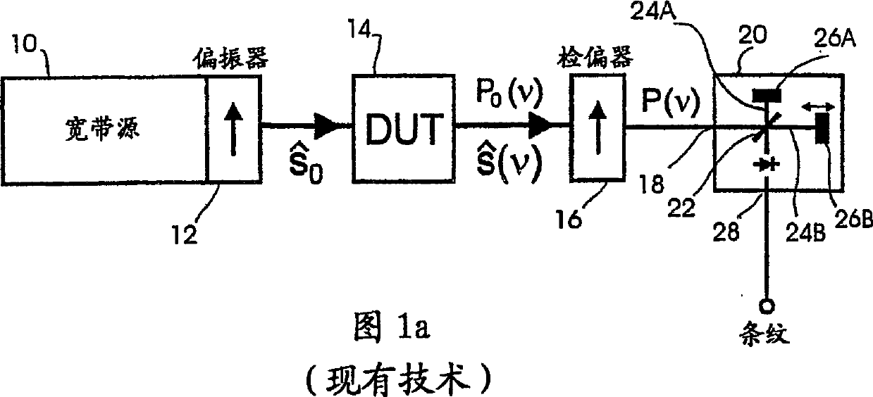
[0031] The known device shown in Figure 1 comprises a broadband polarized light source arrangement comprising a broadband light source 10, such as a light emitting diode, an erbium-doped fiber source, etc., and the device also includes a polarizer 12 (conventional linear polarizer) for polarize the light from the light source 10 and will have the polarization state Polarized light is applied to the input of a device under test (DUT) 14 (such as an optical fiber or other type of waveguide). Through the analyzer 16, which is simply another linear polarizer, the light leaving the DUT 14 whose frequency depends on the polarization state and power P 0 The light of (v) is applied to the input 18 of an interferometer 20, shown as a Michelson interferometer.

[0032] The interferometer 20 includes a beam splitter or splitter 22, such as a semi-reflective plate or a 50-50 fiber coupler inclined at 45°, for separating the light received from the analyzer 16 into two interfering beam...


PUM


Abstract

Apparatus for measuring polarization mode dispersion (PMD) of a device, e.g. a waveguide, comprises a broadband light source ( 10,12 ) for passing polarized broadband light through the device ( 14 ), an interferometer ( 20 ) for dividing and recombining light that has passed through the device to form interferograms, a polarization separator ( 30 ) for receiving the light from the interferometer and separating such received light along first and second orthogonal Feb. 25, 2003 Feb. 25, 2003 polarization states, detectors ( 32 x ,32 y) for converting the first and second orthogonal polarization states, respectively, into corresponding first and second electrical signals (Px(tau),Py(tau)), and a processor ( 36 ) for computing the modulus of the difference and such, respectively, of the first and second electrical signals to produce a cross-correlation envelope (EC(tau)) and an auto-correlation envelope (Ec(tau)), and determining the polarization mode dispersion according to the expression PMD=where and tau is the delay difference between the paths of the interferometer. PMD = 3 2 ⁢ ( sigma 2 - sigma 0 2 ) ⁢ ⁢ sigma 2 = ∫ tau 2 ⁢ E C 2 ⁡ ( tau ) ⁢ ⅆ tau ∫ E C 2 ⁡ ( tau ) ⁢ ⅆ tau ⁢ ⁢ and ⁢ ⁢ sigma 0 2 = ∫ tau 2 ⁢ E A 2 ⁡ ( tau ) ⁢ ⅆ tau ∫ E A 2 ⁡ ( tau ) ⁢ ⅆ tau ( I )

Description

technical field [0001] The present invention relates to methods and apparatus for measuring the polarization mode dispersion (PMD) of optical devices, in particular waveguides used in optical communication systems. Background technique [0002] It is known that PMD can be measured by injecting broadband linearly polarized light into a waveguide, passing the light exiting the waveguide through a linear polarizer, and sending it to a scanning interferometer, where the light exiting the two arms of the interferometer is combined to produce An interferogram, converting the intensity I of said composite light into a corresponding electrical signal, and processing this electrical signal to obtain the PMD from the curve I(τ), which is the intensity I of the light relative to the interferometer The curve of the optical path delay difference τ (hereinafter referred to as delay τ) between the two arms. [0003] As described in US Pat. No. 5,712,704 (Martin et al.), the curve I(τ) exh...

Claims


Application Information

Patent Timeline
Patent Type & Authority Patents(China)
IPC IPC(8): G01M11/00G01J4/04
CPCG01J4/04G01M11/331G01M11/336
Inventor N·西尔
Owner 埃科斯弗公司